Table of Contents
Advertisement
Use
CC1N7451en
20.11.2017
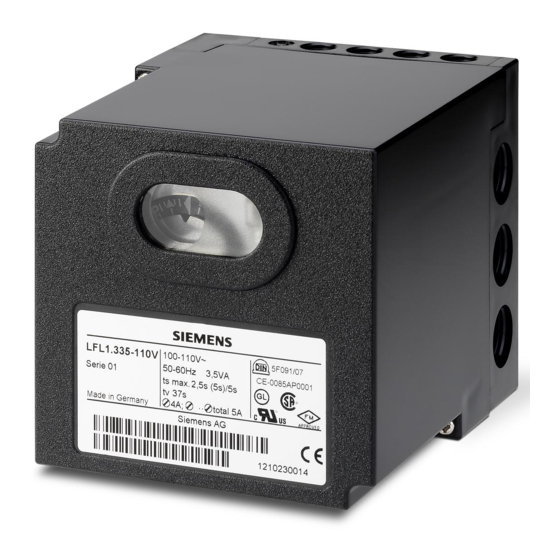
Burner Controls
Burner controls
For gas, oil or dual-fuel forced draft burners of medium to high capacity
For multistage or modulating burners in intermittent operation
With checked air damper control
– with UV detectors QRA2 / QRA4 / QRA10
– and ionization probe
The LFL1... and this Data Sheet are intended for use by OEMs which integrate the
burner controls in their products!
Control and supervision of forced draft burners of direct spark flame or interrupted
pilot construction
For medium to high capacity
For intermittent operation (at least one controlled shutdown every 24 hours)
For universal use with multistage or modulating burners
For use with stationary air heaters (WLE)
For use with dual-fuel burners
Type-tested and approved in accordance with DIN EN 298
The flame supervision is ensured via a flame detector QRA2 / QRA4 / QRA10 or
ionization probe. The difference between 01 series and 02 series is the duration of the
safety time for the pilot burner of burners equipped with pilot gas valves.
For atmospheric burners of high capacity, use the LFL1.638.
Building Technologies Division
7
451
LFL1...
Advertisement
Table of Contents

Related Manuals for Siemens LFL1.322


Summarization of Contents
Burner Controls Overview
Burner Controls Functionality
Details the specific types of burners and capacities the LFL1... controls are designed for.
Application Use Cases
Outlines the various applications and operating modes where the LFL1... burner controls are intended for use.
Supplementary Information
General Safety Warnings
Critical safety instructions to avoid injury, damage, or environmental harm during handling and operation.
Mounting Precautions
Guidance on earthing lug connection and UV radiation precautions during mounting.
Installation Guidelines
Recommendations for wiring, cable routing, and terminal usage to ensure proper installation.
Application and Connection Notes
Flame Detector Electrical Connection
Guidelines for optimal signal transmission and cable routing for flame detectors.
Commissioning Safety Checks
Essential safety checks to perform during plant commissioning and maintenance for safe operation.
Engineering and Connection Details
Remote Reset Functionality
Details on how to connect and use the remote reset function for the burner control.
Switching Capacity Requirements
Specifications for switching devices connected to various terminals for proper operation.
Air Pressure Supervision Setup
Configuration for monitoring air pressure using the LP switch for burner safety.
Compliance and Certifications
Applicable Directives and Standards
List of EU directives and harmonized standards the product complies with for safety and performance.
Regulatory Compliance Verification
Verification of compliance with directives through adherence to specific technical standards.
Note on Household Appliance Standard
Specific note regarding compliance with EN 60335-2-102 for electrical connections.
Eurasian Conformity Mark
Indicates conformity with Eurasian Economic Union requirements.
China RoHS Compliance
Information on hazardous substances and their table as per China RoHS regulations.
Product Certification Details
Table showing certifications for various LFL1... models with plug-in bases and flame detectors.
Product Life Cycle and Design
Disposal and Environmental Notes
Guidance on proper disposal of electronic components in accordance with local legislation.
Mechanical Design Features
Description of the plug-in design, housing, and lockout reset button features.
Housing Component Details
Description of the impact-proof housing and lockout reset button features, including indicators.
Burner Control Type Summary
Timing Parameter Definitions
Explanation of all time variables (t1, t3, TSA, etc.) used in burner sequences and operation.
Optional Accessories
Flame Detector Options
Details on available UV and ionization flame detectors compatible with the burner controls.
Connection Base Options
Information on plug-in bases for burner controls, specifying thread types.
Miscellaneous Accessories
Details on reversed polarity protection accessories for specific regions.
Actuator Accessories
Actuator Types
Overview of different Siemens actuators compatible with burner controls, referencing their data sheets.
Technical Specifications
General Unit Data
Key electrical and physical specifications of the LFL1... burner control unit.
Environmental Operating Conditions
Specifies storage, transport, and operation conditions like temperature and humidity.
Technical Specifications (Continued)
Ionization Probe Flame Supervision
Technical details for flame supervision using an ionization probe, including voltage and current.
UV Detector Flame Supervision
Technical details for flame supervision using UV detectors, including voltage and current.
Detector Current Measurement Circuits
Diagrams and specifications for measuring detector currents for ionization and UV detectors.
Burner Control Functions
2-Stage Direct Spark Flame Operation
Describes the function and sequence for 2-stage direct spark flame burners.
Modulating Direct Spark Flame Operation
Describes the function and sequence for modulating direct spark flame burners.
2-Stage Interrupted Pilot Operation
Describes the function and sequence for 2-stage interrupted pilot burners.
Function Legend
Explanation of symbols and terms used in function diagrams to understand operational sequences.
Burner Control Functionality
General Safety Features
Highlights additional safety features of the LFL1... controls, such as fault detection and checks.
Burner Operation Control
Details on controlling fan motors, pilot valves, actuators, and air dampers during operation.
Flame Supervision Details
Information on ionization and UV detector supervision methods, including network considerations.
Startup Preconditions
Essential input signals and conditions required for burner startup, including switch positions and air pressure.
Startup Sequence Overview
Start Command and Pre-Purge
Initial sequence steps: start command, fan power, and prepurge time with air damper open.
Interval and Air Damper Positioning
Details on interval timing and air damper movement to low-fire position during startup.
Direct Spark Flame Burner Sequence
Specific timing and safety checks, including ignition safety and preignition times for direct spark burners.
Startup Sequence Details
Interrupted Pilot Burner Sequence
Specific timing and safety checks, including ignition safety and second safety times for interrupted pilot burners.
Burner Operation and Controlled Shutdown
Describes burner operation, load control, and controlled shutdown procedures.
Postpurge and Afterburn Times
Details on postpurge time for fan motor and permissible afterburn time for flame signal input.
Fault Handling and Lockout Indication
Lockout Fault Symbol Guide
Explanation of symbols indicating various fault conditions and lockout types within the control sequence.
Lockout Indicator Overview
Visual representation of the lockout indicator and its states corresponding to startup and postpurge.
Lockout Reset Procedure
Instructions for resetting the burner control after a lockout event, including button press duration.
Circuit Connection Diagrams
Circuit Diagram Overview
Main connection diagram illustrating terminal connections and components for burner controls.
Switchgear Sequence Charts
Switchgear Timing and Control Outputs
Charts showing switchgear states and control outputs at specific terminals over time.
Connection Examples and Program Sequences
Safety Time Extension Example
Example for doubling safety time in direct spark flame burners by linking specific terminals.
Burner Without Air Damper Configuration
Example for burners lacking an air damper control, requiring linked terminals 8 and 6.
Reversed Polarity Protection Example
Example showing reversed polarity protection using AGM30, which simulates flame on mains cable switch.
2-Stage Direct Spark Flame Burner Example
Example connection and sequence for a 2-stage direct spark flame burner with load control.
Connection Examples and Program Sequences (Continued)
Modulating Burner Connection Example
Example for connecting a modulating direct spark flame burner with load control via actuators.
Interrupted Pilot Burner Connection Example
Example for connecting a 2-stage interrupted pilot burner, controlled and supervised by a 01 series control.
Comprehensive Legend
Component Symbol Definitions
Explanation of symbols for components like valves, motors, switches, and detectors.
Signal and Input Definitions
Definitions for permissible and required input signals, including those for detector tests.
Sequence State Definitions
Definitions for sequence states like startup, operation, shutdown, and their corresponding symbols.
Comprehensive Legend (Continued)
Lockout Position Indicators
Description of lockout indications when no input signal is present, referencing control sequence events.
Time Table Definitions
Defines all time variables (t1, t3, TSA, etc.) used in sequences, providing their meaning and context.
Product Dimensions
Unit Physical Dimensions
Provides detailed dimensions of the LFL1... unit and plug-in base in millimeters.
Need help?
Do you have a question about the LFL1.322 and is the answer not in the manual?
Questions and answers