
Related Manuals for ACV Smart ME 300


Summary of Contents for ACV Smart ME 300
- Page 1 INSTALLATION, OPERATION AND MAINTENANCE INSTRUCTIONS, for the User and the Installer SMART Line Smart ME 200 - 300 - 400 - 600 - 800 A1003499 - 661Y2000 • C...
-
Page 2: Table Of Contents
PRODUCT INFORMATION ................5 Energy labelling ............................... 5 Rating Plate .................................. 6 USER'S GUIDE .....................7 Control panel (Only Smart ME 200 - 300 - 400) ................7 APPLIANCE DESCRIPTION ................8 TECHNICAL CHARACTERISTICS ............10 Main characteristics : Smart ME 200 - 300 ..................10 Dimensions : Smart ME 200 - 300 ...................... - Page 3 TABLE OF CONTENTS Connection to the primary circuit ......................32 Examples of different possible combinations of the Smart ME ........33 Smart ME tank used as electric DHW tank only ................34 STARTING UP ...................35 Safety instructions to fill the tank ......................35 Filling ....................................36 Checks before starting up ..........................38...
-
Page 4: General Recommendations
• The part number (P/N) and serial number (S/N) of the appliance are indicated on its rating plate and must be provided to ACV in case of warranty claim. Failure to do so will make the claim void. •... -
Page 5: Product Information
PRODUCT INFORMATION ENERGY LABELLING Smart ME : A1003499 - 661Y2000 • C... -
Page 6: Nl Rating Plate
PRODUCT INFORMATION RATING PLATE Smart ME 120 Smart ME 600 / 800 Smart ME 200 Smart ME 300 / 400 Smart ME : A1003499 - 661Y2000 • C... -
Page 7: User's Guide
2. Manual reset high limit thermostat - to restart the tank after overheating of the primary circuit. 3. Connection plug - to connect the electrical power supply. Thermometer - indicates the temperature of the DHW. (Only Smart ME 200 - 300 - 400) Smart ME : A1003499 - 661Y2000 • C... -
Page 8: Appliance Description
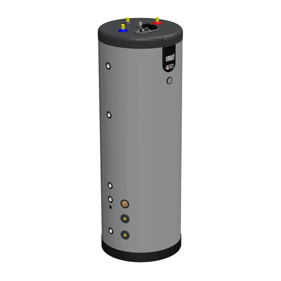
APPLIANCE DESCRIPTION MODELS - Smart ME 200 - 300 - 400 - 600 - 800 High efficiency storage water tanks, multi-energy type, to be installed on the floor. Possibility to heat by coil, by heat transfer fluid or by optional electrical resistance (except for Smart ME 800). - Page 9 APPLIANCE DESCRIPTION 1. Manual air bleed valve 8. Dry well 9. Outer steel tank (primary circuit) 2. Polyurethane foam insulation 3. Polypropylene shell 10. Steel coil 4. Dip tube 11. Polypropylene bottom lid 5. Electrical heating element (optional) 12. Soft insulation 6.
-
Page 10: Technical Characteristics
TECHNICAL CHARACTERISTICS TECHNICAL CHARACTERISTICS MAIN CHARACTERISTICS : SMART ME 200 - 300 Smart ME Main characteristics Total capacity Primary circuit capacity (heating) 95.7 DHW circuit capacity Coil capacity Primary pressure drop* mbar 41.6 51.2 Coil pressure drop mbar Tank heating surface m²... -
Page 11: Dimensions : Smart Me 200 - 300
TECHNICAL CHARACTERISTICS DIMENSIONS : SMART ME 200 - 300 Smart ME 200 Smart ME 300 Smart ME : A1003499 - 661Y2000 • C... -
Page 12: Main Characteristics : Smart Me 400 - 600 - 800
TECHNICAL CHARACTERISTICS MAIN CHARACTERISTICS : SMART ME 400 - 600 - 800 Smart ME Main characteristics Total capacity Primary circuit capacity (heating) DHW circuit capacity Coil capacity Primary pressure drop* mbar 53.5 58.5 Coil pressure drop mbar Tank heating surface m²... -
Page 13: Dimensions : Smart Me 400 - 600 - 800
TECHNICAL CHARACTERISTICS DIMENSIONS : SMART ME 400 - 600 - 800 Smart ME 400 Smart ME 600 Ø 270 Ø 910 Smart ME 800 Ø 270 Ø 990 Smart ME : A1003499 - 661Y2000 • C... -
Page 14: Heating Connections
Connections dimensions Models Heating Coil Optional electrical connection connection heating element connection Smart ME 200 Ø 1" [F] Ø 1" [M] Ø 1"½ [F] Smart ME 300 Ø 1" [F] Ø 1" [M] Ø 1"½ [F] Smart ME 400 Ø 1" [F] Ø... - Page 15 TECHNICAL CHARACTERISTICS Smart ME 600 Smart ME 800 Smart ME : A1003499 - 661Y2000 • C...
-
Page 16: Domestic Hot Water Connections
TECHNICAL CHARACTERISTICS DOMESTIC HOT WATER CONNECTIONS Pipe dimensions Models Cold / hot water Auxiliary connections connections Smart ME 200 Ø 3/4" [M] Ø 3/4" [M] Smart ME 300 Ø 3/4" [M] Ø 3/4" [M] Smart ME 400 Ø 3/4" [M] Ø... -
Page 17: Domestic Hot Water Performances
TECHNICAL CHARACTERISTICS DOMESTIC HOT WATER PERFORMANCES Smart ME DHW performance : Heating source = Coil * L/10' 40°C [∆T = 30K] Peak flow at L/10' 45°C [∆T = 35K] L/10' 60°C [∆T = 50K] 40°C [∆T = 30K] Constant flow at 45°C [∆T = 35K] 60°C [∆T = 50K] L/60'... -
Page 18: G3 Requirements And Guidance - Uk Only
TECHNICAL CHARACTERISTICS G3 REQUIREMENTS AND GUIDANCE - UK ONLY Discharge pipe from safety valves The Building Regulation G3 requires that any discharge from an unvented system is conveyed to where it is visible, but will not cause danger to persons in or about the building. The tundish and discharge pipes should be fitted in accordance with the requirements and guid- ance notes of Building Regulation G3. - Page 19 TECHNICAL CHARACTERISTICS Discharge pipe D2 3.56 The discharge pipe (D2) from the tundish should: (a) have a vertical section of pipe at least 300mm long below the tundish before any elbows or bends in the pipework; and (b) be installed with a continuous fall thereafter of at least 1 in 200. 3.57 The discharge pipe (D2) should be made of: (a) metal;...
- Page 20 TECHNICAL CHARACTERISTICS 3.63 The discharge would consist of high temperature water and steam. Asphalt, roofing felt and non-metallic rainwater goods may be damaged by such discharges. temperature relief valve to tundish 600mm maximum Tundish 300mm minimum Discharge below fixed Metal discharge pipe (D2) tundish with grating (3.61 gives continuous fall.
- Page 21 TECHNICAL CHARACTERISTICS Worked example of discharge pipe sizing Figure on the left shows a G1/2 temperature relief valve with a discharge pipe (D2) having 4 No. elbows and length of 7m from the tundish to the point of discharge. From Table: Maximum resistance allowed for a straight length of 22mm copper discharge pipe (D2) from a G1/2 temperature relief valve is 9.0m.
-
Page 22: Maximum Operating Conditions
Optional heating element for Smart ME The models Smart ME 200 - 300 - 400 - 600 can be installed with a self- controlled heating element with built-in control safety thermostats. The control thermostat of the tank cannot control the heating element. - Page 23 TECHNICAL CHARACTERISTICS Wiring diagram : Smart ME 200 - 300 - 400 Manual reset high limit thermostat Black Brown Control thermostat [60/80°C] Orange White Y/Gr. Yellow/Green Y/Gr Y/Gr Optional kit thermostat : Smart ME 600 - 800 : (10800260) Control thermostat [60/80°C]...
-
Page 24: Ru Installation
INSTALLATION PACKAGE CONTENTS The Smart ME 200 - 300 - 400 appliances are delivered assembled, tested and packed. The Smart ME 600 - 800 appliances are delivered, tested and packed separately. At product reception and after removal of packaging, check the package contents and that the appliance is free of damages. -
Page 25: Tools Required For The Installation
INSTALLATION TOOLS REQUIRED FOR THE INSTALLATION For installation of the soft casing, refer to "Preparation of the Tank (Smart ME 600 - 800)", page General remark • Make sure to place the rating plate on the outer casing of the tank, so that it is easily accessible and readable. -
Page 26: Safety Instructions
INSTALLATION SAFETY INSTRUCTIONS General remarks • Connections (electrical, hydraulic) must be carried out in accordance with applicable standards and regulations. • If the water drawing off point is far from the tank, installing an auxiliary DHW loop can allow to get hot water more quickly at all times. Essential instructions for the correct operation of the system •... - Page 27 The upper hot water layer may then reach very high temperatures. • ACV recommends using a pre-set thermostatic mixing valve in order to provide hot water at a maximum of 60°C. • Water heated to wash clothes, dishes and for other uses can cause serious burns.
-
Page 28: Preparation Of The Tank (Smart Me 600 - 800)
INSTALLATION PREPARATION OF THE TANK (SMART ME 600 - 800) Smart ME : A1003499 - 661Y2000 • C... - Page 29 INSTALLATION Install the rating plate sticker here. Smart ME : A1003499 - 661Y2000 • C...
-
Page 30: Connection
• Hot water can burn! ACV recommends using a pre- set thermostatic mixing valve in order to provide hot water at a maximum of 60°C. Essential instructions for the correct operation of the system •... -
Page 31: Connection To The Dhw Circuit
INSTALLATION CONNECTION TO THE DHW CIRCUIT Filling valve Pressure reducing valve (set at 4.5 bar) Check valve DHW expansion vessel Safety valve (set at 7 bar) Drain valve Draw-off tap Pressure gauge Grounding 10. Stop valve 11. Thermostatic mixing valve 12. -
Page 32: Connection To The Primary Circuit
INSTALLATION CONNECTION TO THE PRIMARY CIRCUIT Primary circuit filling valve Expansion vessel Charging pump Pressure gauge Check valve Safety valve (set at 3 bar) Primary circuit stop valve Drain valve Cold water Hot water Smart ME : A1003499 - 661Y2000 • C... -
Page 33: Examples Of Different Possible Combinations Of The Smart Me
INSTALLATION EXAMPLES OF DIFFERENT POSSIBLE COMBINATIONS OF THE SMART ME Smart ME combined with a heat pump, solar panels and floor heating system. Prestige Smart ME combined with a boiler and solar panels. Smart ME : A1003499 - 661Y2000 • C... -
Page 34: Smart Me Tank Used As Electric Dhw Tank Only
INSTALLATION SMART ME TANK USED AS ELECTRIC DHW TANK ONLY Do not power the heating element if the outside tank is not filled and bled. System filling valve 2. Safety valve set to 3 bar Expansion vessel 4. Isolating valve, heating system Pressure gauge Plug all unused connections Essential instruction for the correct operation of the installation... -
Page 35: Starting Up
STARTING UP STARTING UP SAFETY INSTRUCTIONS TO FILL THE TANK Essential instructions for the safety of persons and the environment • The DHW tank must always be filled and pressurised before filling and pressurising the primary circuit. • Do not use vehicle antifreeze. This can cause serious injury or death, or damage facilities. -
Page 36: Filling
STARTING UP FILLING Essential instruction for the correct operation of the system • The DHW tank must always be filled and pressurised before filling and pressurising the primary circuit. FILLING THE DHW TANK (Figure 1) General remark • Connect the safety valve outlet to the sewer. To fill the tank, open a hot water tap (2) located at the highest point of the system. - Page 37 STARTING UP Figure 1 Cold water Hot water Figure 2 Smart ME : A1003499 - 661Y2000 • C...
-
Page 38: Checks Before Starting Up
STARTING UP CHECKS BEFORE STARTING UP • Check that the safety valves (DHW and primary) are correctly installed and that the outlets are connected to the sewer. • Check that the DHW tank and the primary circuit are filled with water. •... -
Page 39: Maintenance
MAINTENANCE MAINTENANCE PERIODIC CHECKS BY THE USER • Check the pressure of the primary circuit pressure gauge: it should be between 0.5 and 1.5 bar. • Visually inspect, on a regular basis, the valves, connections and accessories in order to detect any leaks or malfunction. -
Page 40: Draining
MAINTENANCE DRAINING Essential instruction for the safety of persons and the environment • The water coming out of the drain valve is very hot and can cause very severe burns. Make sure the area around the hot water flow is clear of people. Essential instruction for the electrical safety •... -
Page 41: Bringing Back Into Service After Maintenance
MAINTENANCE DRAINING THE DHW TANK (Figure 4) To drain the hot water heater’s DHW tank: Open fully the hot water tap (3) for at least 60 minutes to make sure the DHW tank has cooled down sufficiently. Close the filling valve (1) and the stop valve (4). Connect the drain valve (2) to the sewer using a flexible hose. -
Page 42: Fault Finding
Models Smart ME 200 - 300 - 400 Smart ME 200 - 300 - 400 + electric heating element Smart ME 600 + control thermostat kit Smart ME 600 + electric heating element Smart ME 800 + control thermostat kit...
Need help?
Do you have a question about the Smart ME 300 and is the answer not in the manual?
Questions and answers