Table of Contents
Advertisement
STANDARD HEIGHT
FRAME & HEADER KITS
EVOMAX
30 - 150
30P - 80P
EVOMAX 2
30 - 150
30P - 120P
When replacing any part on this appliance, use only spare parts that you can be assured conform to the safety and performance specification that we
require. Do not use reconditioned or copy parts that have not been clearly authorised by Ideal.
For the very latest copy of literature for specification and maintenance practices visit our website www.idealcommercialboilers.com
where you can download the relevant information in PDF format.
April 2019
UIN 220380 A01
Advertisement
Table of Contents

Related Manuals for ideal commercial Evomax 2 150


Summarization of Contents
1 INTRODUCTION
Introduction to Frame & Header Kits
Details the purpose and application of Evomax multiple boiler frame and header kits for spreading heat output.
2 CASCADE SYSTEM DESCRIPTION
Frame and Header Kit Design Options
Explains the side-by-side and back-to-back configuration options for Evomax multiple boiler systems.
Multiple Boiler Installation Overview
Covers installation of 2 to 6 boilers using water and gas headers with various connection types.
Hydronic Isolation: Low Loss Header & Plate Heat Exchanger
Explains the function of low loss headers for flow separation and heat transfer in hydronic systems.
Output Control and Cascade Options
Discusses wiring pumps for controlled pump over-run and optional cascade control accessories.
Gas Supply Configuration
Details gas supply configurations for Natural Gas and LPG/Propane for Evomax and Evomax 2 boilers.
System Assembly Considerations
Provides guidance on locating and securing frames for multi-boiler installations, ensuring stability.
Safe Handling Procedures
Outlines essential safety precautions and techniques for handling and maneuvering boilers and kits.
3 MULTIPLE BOILER SYSTEM COMPONENTS
General System Components
Lists the primary components of multiple boiler systems, including frame kits, headers, and hardware.
Main Water Headers
Describes water flow and return headers sized for different configurations and output requirements.
Gas Header Assembly
Details the custom-manufactured 2" manifold used for gas supply in multi-boiler setups.
Optional Low Loss Headers (Mixing Header)
Explains the features of optional mixing headers, including air vents and drain points.
Boiler Shunt Pump Requirements
Discusses the role of pump kits and external controls in ensuring optimal flow around appliance circuits.
Boiler Connection Kit Components
Details the connection kit components for boiler flow and return, including valves and seals.
Free-Standing Frame Options
Describes options for mounting boilers on free-standing frames for in-line and back-to-back configurations.
Installation Area and Dimensions Guide
Provides guidance on required clearances for installation, servicing, and flue system installation.
4 WALL MOUNTED INSTALLATION
Wall Mounted Side By Side Option
Step-by-step instructions for wall mounting boilers side-by-side, including template use and plate fixing.
5 FRAME KIT INSTALLATION
Side By Side Frame Kit Mounting Procedure
Details the procedure for assembling and securing side-by-side frame kits, including floor bolting.
Boiler Mounting on Frames or Plates
Instructions for mounting boilers onto wall plates or side-by-side frame kits.
6 HEADER KIT ASSEMBLY & CONNECTIONS
Fitting Mixing Header and Blanking Flanges
Describes fitting the mixing header and blanking flanges in chosen positions on the header assembly.
Header Kit Assembly Procedure
Step-by-step guide for assembling the header kit to the frame legs and connecting components.
Gas Connection Fitting
Procedure for connecting the gas supply to the boiler and header assembly.
Pressure Relief Valve Connection Safety
Ensures each boiler's pressure relief connection is piped safely.
Condensate Siphon Fitting
Details the fitting of the condensate siphon to the boiler and piping to the drain.
7 INSTALLATION DRAWINGS
7.1 General System Formats
Outlines the three available formats for multiple boiler systems: wall-mounted and free-standing frame configurations.
7.2 Side By Side Frame Kit Configurations
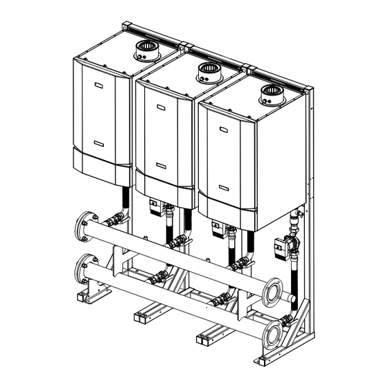
Presents installation drawings for side-by-side frame kit configurations with various boiler numbers and types.
7.3 Back To Back Frame Kit Configurations
Presents installation drawings for back-to-back frame kit configurations with various boiler numbers and types.
8 ELECTRICAL CONNECTIONS & WIRING
Boiler Pump Speed Control & Wiring Diagram
Provides the electrical connections and wiring diagram for boiler pump speed control and external controls.
9 COMMISSIONING AND TESTING
Electrical and Gas Safety Checks
Emphasizes the need for electrical and gas safety checks after installation, similar to individual boiler commissioning.
Pump Setting Guide
Guides users on setting the pump types (UPML/UPMXXL) for optimal performance in different configurations.
Need help?
Do you have a question about the Evomax 2 150 and is the answer not in the manual?
Questions and answers