Table of Contents
Advertisement
These instructions contain operating information and should be left with the unit.
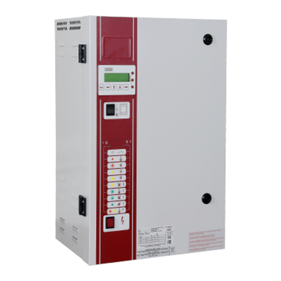
Electrode Boiler Units
LE
Installation & Operation Manual
Edition 3.2.2
(For use with Software version 7.1 & subsequent issues)
Installation in countries covered by EC Directives:
This product meets the requirements of the RoHS Directive 2002/95/EEC
This product will meet the requirements of the Low Voltage Safety Directive
EEC and the EMC
2006/95/
Directive
EEC when installed in accordance with the instructions contained in this manual.
2004/108/
Failure to comply with these instructions may invalidate the manufacturer's warranty or any
certificate/declaration of conformance requested to be supplied with the unit.
Advertisement
Table of Contents

Related Manuals for Vapac LE18


Summarization of Contents
Important Installation Points
Important Electrical Connection Items
Guidelines for connecting control/security circuits and transformer use.
Important Maintenance Items
Safety and precautions for maintenance, including ESD sensitivity.
1.0 Installation.
1.1 Vapac LE unit dimensions
Details cabinet dimensions for LE05, LE09, and LE18 models.
1.2 Positioning the steam pipes
Guidelines for steam pipe and hose installation, slope, and connections.
1.3 Plumbing Considerations.
Specifies water quality limits and drain connection requirements.
1.4 Electrical Connections
Covers power supply, EMC, and control circuit wiring and connections.
1.5 Cylinder Electrical demand loads
1.5.1 LExx Units
Lists electrical demand loads for LExx units across various voltages/phases.
1.5.2 LExxP Units
Lists electrical demand loads for LExxP units across various voltages/phases.
1.6 Control Circuit Connections
1.6.1 Control Circuit Wiring
Guidance on screened cables, conduit, and grounding for control signals.
1.6.2 Proportional Control
Details available input signals for proportional control (0-5V, 4-20mA, etc.).
1.6.3 Control Signal Selection
How to select control signals using keypad or jumpers.
1.6.4 On/Off Control
Operation modes for On/Off control using humidistats.
1.6.5 Sensing Head
Connecting external sensing heads and frost protection.
1.6.6 Security Circuit / E.P.O. Shutdown
Connections for E.P.O. switches, interlocks, and shutdown features.
1.6.7 Load Shed Option
How to enable load shedding for power limitation during peak periods.
1.6.8 Master/Slave System
How to interconnect units for master/slave operation up to 10 cylinders.
2.0 Start-Up / Operation
2.0.1 Start-up check list
Key checks before starting up the unit, including water and power.
2.0.2 Start-Up Instructions
Procedures for initial setup and configuration via display or jumpers.
2.0.3 Commissioning/Start-Up
How the unit starts and monitors conductivity after initial setup.
2.0.4 Features of VAPANET Electode Boiler Unit
Overview of Vapanet control features like foaming protection and auto-shutdown.
2.1 Service Advice
2.1.1 Procedure for cylinder Exchange.
Step-by-step guide for replacing a steam cylinder.
2.1.2 Typical Cylinder / Electrode Layouts
Diagrams showing electrode and cylinder configurations for different sizes.
2.2 Service and Maintenance
2.2.1 Feed Valve with Strainer
Instructions for cleaning the feed valve strainer.
2.2.2 Drain Pump
Procedure for removing and replacing the drain pump.
3.0 Location of Indicators and Controls
3.1 Positioning of Indicators and controls on Vapac ® Vapanet ® LE Units.
Identifies locations of user LEDs, switches, and displays on the unit fascia.
3.2 Initial Set-up
User LEDs
Explains the states of User LEDs during initialisation and setup.
3.3 Normal Run / Standby / Start-up – No User Intervention Required
User LED states for Run/Standby/Shutdown
Describes normal operational states (Run, Standby, Start-up) indicated by LEDs.
3.4 Fault / Service Indications – Requiring Operator Intervention.
Fault and Service Indications
Lists LED indications for faults and required operator intervention.
3.4.1 To Postpone the Sevice:
How to postpone service alerts for service interval or low output.
3.5 Fascia Label symbols
3.6 Other Options
Describes selectable options like Feed With Drain and Frost Protection.
4.0 Trouble-shooting Check List
Preliminary Troubleshooting
Initial checks for power, security circuit, and feed/drain faults.
Unit On-Line but inadequate or no steam production.
Checks for issues causing low or no steam production (contactor, SSRs).
Specialized check of the Solid State Relay
Procedure for testing and replacing Solid State Relays (SSRs).
Appendix 1.
A Guide to Positioning Steam Pipes:
Guidance on steam pipe orientation, slope, and elbow restrictions.
Appendix 2
A Guide to Positioning Multipipes:
Guidance on positioning multiple steam pipes and hose support.
Need help?
Do you have a question about the LE18 and is the answer not in the manual?
Questions and answers