Table of Contents
Advertisement
These instructions contain operating information and should be left with the unit.
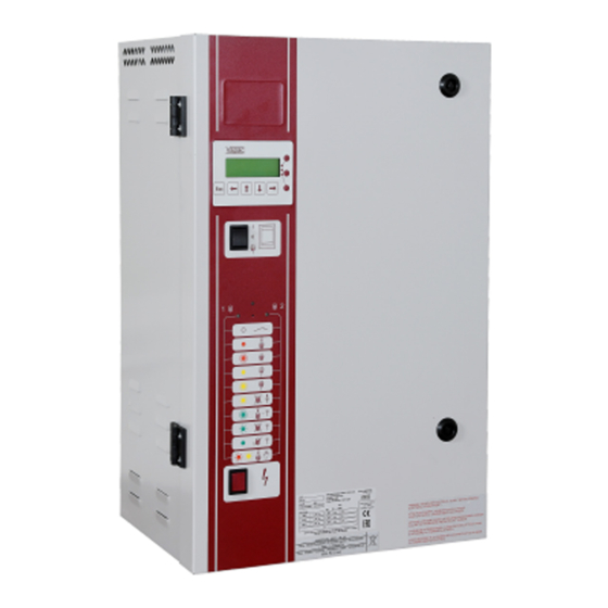
Electrode Boiler Units
LE
Installation & Operation Manual
Edition 3.2.2
(For use with Software version 7.1 & subsequent issues)
Installation in countries covered by EC Directives:
This product meets the requirements of the RoHS Directive 2002/95/EEC
This product will meet the requirements of the Low Voltage Safety Directive
EEC and the EMC
2006/95/
Directive
EEC when installed in accordance with the instructions contained in this manual.
2004/108/
Failure to comply with these instructions may invalidate the manufacturer's warranty or any
certificate/declaration of conformance requested to be supplied with the unit.
Advertisement
Table of Contents

Subscribe to Our Youtube Channel
Related Manuals for Vapac VapaNet Series


Summary of Contents for Vapac VapaNet Series
- Page 1 These instructions contain operating information and should be left with the unit. Electrode Boiler Units Installation & Operation Manual Edition 3.2.2 (For use with Software version 7.1 & subsequent issues) Installation in countries covered by EC Directives: This product meets the requirements of the RoHS Directive 2002/95/EEC This product will meet the requirements of the Low Voltage Safety Directive EEC and the EMC 2006/95/...
-
Page 2: Table Of Contents
Drain Pump .......................... 24 Location of Indicators and Controls .................... 25 Positioning of Indicators and controls on Vapac ® Vapanet ® LE Units........ 25 Initial Set-up ..........................26 Normal Run / Standby / Start-up – No User Intervention Required ........27 Fault / Service Indications –... -
Page 3: Important Installation Points
NB if the controller output is referenced to ground, it is important that the “leg” which is connected to ground at the controller is also connected to ground at the Vapac unit. Grounding the opposite “leg” will cause damage to the controller and/or the Vapac control PCB. -
Page 4: Installation
Do leave minimum gap between the top of an RDU and Don’t position an RDU to discharge directly over the ceiling as per table in fig 2. expensive equipment, desks or stored materials 1.1 Vapac LE unit dimensions Left: 172.0 203.0 Cabinet Size 1. - Page 5 Cabinet Size 2. Covering model references: LE30 – All LE45 – All LE55 - All Left: Top view of unit showing steam outlet position (54 mm spigot) Steam Outlet 54 mm Below: Rear view of unit showing wall mounting points. Gland Plate Right: 120 X 120...
- Page 6 Cabinet Size 4. Covering model references: LE60 – All LE90 – All LE110 – All Left: Top view of unit showing steam outlet positions (54 mm spigots) Below: Rear view of unit showing wall mounting points. Steam Outlets 54 mm 20.5"(520) Left: Right:...
- Page 7 Cabinet Sz 1 with RDU Dimensions Cabinet size 2 with Dimensions RDU 30 kg/h A = 602mm B = 205mm RDU 45 kg/h A = 842mm B = 360mm Clearance around LE Units Unit LE05 All 1000 (No RDU) LE05 All 1000 (With RDU) LE09 All...
-
Page 8: Le Weights
Do's stainless steel pipe coupling length to allow steam pipe with for line movement and Do use Vapac steam hose or well insulated copper Insulation. expansion. Coupling clamp with Hose clips each end. pipe. Do keep steam hose as short as possible (under 2m Fig 6 for max efficiency). -
Page 9: Plumbing Considerations
Do ensure drain line pipe size will accommodate water being Do install a stop-valve/Shut-off valve and a strainer close to drained at the same time from all the Vapac units which the unit. are connected to it. -
Page 10: Electrical Connections
Important Power Connection Information Vapac 24V and 9 V secondary Transformer Primary supply connections: Vapac units are wired to allow connection to alternative site Voltages. Make the following simple checks before connecting the power supply:- Move the BROWN connection on the VAPANET transformer primary winding circuit to... -
Page 11: Power Supply Connection
1.4.2 Power Supply Connection The unit requires the following connections as shown in the diagram below 1.4.2.1 Volt free alarm outputs The unit has connections for volt free alarm outputs these are on the three double terminals next to the main power input terminals. The top terminals are for unit volt free fault alarm as follows: common for fault alarm Normally closed when no fault... -
Page 12: Electrical Connections
Electrical Connections 1.4.4 Cable Entry Provision The wiring to the Vapac should be done by a qualified Cable glands must be used to ensure cables are held electrician. The external overcurrent protection and wiring securely at the entry position. All Vapac cabinets are should comply with the appropriate Regulations and Codes equipped with a removable gland-plate. - Page 13 Power connection details for LExx Units (Units without Solid State Relays). Power connection Details for LExxP Units (Units fitted with Solid State Relays) 200 – 250 V 1Ph. N + earth 200 – 250 V 2Ph. + earth 380 – 440 V 2Ph + earth TRANSFORMER PRIMARY 380 –...
-
Page 14: Cylinder Electrical Demand Loads
Cylinder Electrical demand loads 1.5.1 LExx Units Model Ref. LE05 LE09 Nominal Output Kg/hr Nominal Output lb/hr 19.8 19.8 19.8 19.8 19.8 19.8 Voltage Power input rating 3.71 3.72 3.81 3.75 3.77 6.76 6.68 6.86 6.72 Electrical Supply Ph's Ph+N or Ph+N or Ph+N or Ph+N or... - Page 15 Model Ref. LE45 LE55 Cylinder Nominal Output Kg/hr Nominal Output lb/hr 96.8 Voltage Power input rating 32.66 33.39 33.85 33.65 33.54 33.39 41.37 40.91 41.07 41.37 Electrical Supply Ph's No. of electrodes Full load Current Maximum overcurrent 108.9 96.8 59.4 56.1 53.9 50.6...
- Page 16 Model Ref. LE110 Cylinder Nominal Output Kg/hr Nominal Output lb/hr Voltage Power input rating N.A. N.A. N.A. N.A. 41.37 41.37 40.91 40.91 41.07 41.07 41.37 41.37 Electrical Supply Ph's N.A. N.A. N.A. N.A. No. of electrodes N.A. N.A. N.A. N.A. Full load Current N.A.
-
Page 17: Lexxp Units
1.5.2 LExxP Units Model Ref. LE05P LE09P Nominal Output Kg/hr Nominal Output lb/hr 19.8 19.8 19.8 19.8 19.8 19.8 Voltage Power input rating 3.73 3.71 3.78 3.81 3.78 3.83 6.71 6.76 6.77 6.79 6.74 Electrical Supply Ph's Ph+N or Ph+N or Ph+N or Ph+N or Ph+N or... - Page 18 Model Ref. LE45P Cylinder Nominal Output Kg/hr Nominal Output lb/hr Voltage Power input rating 33.79 33.85 33.93 33.45 Electrical Supply Ph's No. of electrodes Full load Current Maximum overcurrent 68.2 64.9 62.7 58.3 Fuse Rating/phase Supply cable terminals Wiring diagram A4-LZD-561 Cabinet size Model Ref.
-
Page 19: Control Circuit Connections
“leg” which is ground must be the one linked to terminal 7. Vapac PART No. 1150630 1.6.2 Proportional Control The VAPANET Electrode Boiler (LExxP) models can all be operated by either a potentiometric signal, a lonworks network signal or by one of 6 standard proprietary DC analogue signals. -
Page 20: Sensing Head
1.6.5 Sensing Head The units are designed to operate using a sensing head, supplied by Vapac Humidity Control Ltd. which should be connected as shown below. Other propriety sensing heads which give a DC signal may also be used, providing the control signal is connected to control terminals 5 &... -
Page 21: Master/Slave System
Link if control Not required for Not required for signal is mA slave unit. slave unit. current only. Vapac PART No. 1150630 Vapac PART No. 1150630 Network Expansion to slave units 2 to 9 or other network components. Customers terminals within unit... -
Page 22: Start-Up / Operation
Water supply and Drain Connections: nominating: the type/quality of the supply these should be connected as indicated water. under Plumbing and in accordance with the nominating: the control signal (or Vapac sensor relevant local regulations. An isolation valve when being used). should adjacent to the unit. -
Page 23: Service Advice
With hard waters, a more frequent cylinder exchange must be expected and cylinder exchange 2 or 3 times a year can be the average situation. The normal scaling up of the Vapac steam cylinder is outside the Vapac warranty. 2.1.1 Procedure for cylinder Exchange. -
Page 24: Feed Valve With Strainer
Steam and Condensate Hoses The hoses used with and in the Vapac should be inspected at the normal service visits as part of normal maintenance. At the first signs of deterioration, a hose should be removed and replaced. -
Page 25: Location Of Indicators And Controls
Location of Indicators and Controls Positioning of Indicators and controls on Vapac ® Vapanet ® LE Units. Vapac Reset Button Alpha-Numeric Vapac Display Cylinder 1 On/Off/Drain Switch Cylinder 1 On/Off/Drain Switch Cylinder 2 On/Off/Drain Switch Cylinder 2 On/Off/Drain Switch User LED's... -
Page 26: Initial Set-Up
Initial Set-up User LEDs During the initialisation process the User LEDs can be in one of the following states User LED State Description RED Flashing Unit initialising. If remains in this state, then unit does not a valid UCP1 fitted. 2 second period UCP1 valid. -
Page 27: Normal Run / Standby / Start-Up - No User Intervention Required
Normal Run / Standby / Start-up – No User Intervention Required Once the unit has initialised User LED 1 refers to cylinder 1, while User LED 2 refers to Cylinder 2. For combinations of LED 1 and LED 2 being off, RED or RED Flashing refer to following table. -
Page 28: Fault / Service Indications - Requiring Operator Intervention
When the constant amber “drain fault” indication is showing, press the unit “fault reset” button, which is located on the fascia above the “Vapac” Logo. Service Interval Expired / Low Output: Will be seen if either of the following occur. -
Page 29: To Service The Unit
When the alarm is repeated, it should be serviced immediately – and not postponed further. 3.4.2 To Service the unit: Press the reset button: This will cause the appropriate LED to change to constant “amber”, the external alarm to be reset. -
Page 30: Fascia Label Symbols
Fascia Label symbols Network Button Network LED (Service Pin) (Red) Cylinder 2 Cylinder 1 (If fitted) User LED1 User LED2 Red/Green/Amber Red/Amber/Green Unit Off Unit Off On-line On-line Standby Standby Drain Fault Drain Fault Feed Fault Feed Fault Over Over Current Current Service Interval... -
Page 31: Trouble-Shooting Check List
2) Ensure that the humidifier has an operational level of water in the cylinder. Switch unit on and check that the display indicates “Vapac on line”. 3) Apply the voltmeter, set to the full line Voltage, across the output terminals of the SSR being tested (i.e. -
Page 32: Wiring Diagram
Wiring diagram... -
Page 43: A Guide To Positioning Steam Pipes
Appendix 1. A Guide to Positioning Steam Pipes: Vapac Humidity Control Ltd. Issue this as a guide only, and accept no responsibility for the positioning of any pipes in a system. This remains the responsibility of the Project Design Engineer. - Page 44 NB. The duct should be clear of obstructions, transformations and bends until the steam has been absorbed into the airflow. A guide to calculating this distance is available from W > 200 Vapac – Part Number 0411047. October 02 Fig 3 Fig 4...
-
Page 45: A Guide To Positioning Multipipes
Appendix 2 A Guide to Positioning Multipipes: Vapac Humidity Control Ltd. Issue this as a guide only, and accept no responsibility for the positioning of any pipes in a system. This remains the responsibility of the Project Design Engineer. Notes:... - Page 46 Made in England by: April 2014 Vapac Humidity Control Ltd. Printed in Great Britain Vapac Humidity Control Ltd. reserve the right to change the design or specification of the equipment described in this manual without prior notice. 0410270...
Need help?
Do you have a question about the VapaNet Series and is the answer not in the manual?
Questions and answers