Table of Contents
Advertisement
These instructions contain operating information and should be left with the unit.
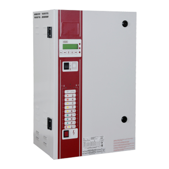
Electrode Boiler Units
LE
Installation & Operation Manual
Edition 3.2.2
(For use with Software version 7.1 & subsequent issues)
Installation in countries covered by EC Directives:
This product meets the requirements of the RoHS Directive 2002/95/EEC
This product will meet the requirements of the Low Voltage Safety Directive
EEC and the EMC
2006/95/
Directive
EEC when installed in accordance with the instructions contained in this manual.
2004/108/
Failure to comply with these instructions may invalidate the manufacturer's warranty or any
certificate/declaration of conformance requested to be supplied with the unit.
Advertisement
Table of Contents

Related Manuals for Vapac LE30


Summarization of Contents
Important Installation Points
Important Electrical Connection Items
Key electrical connection considerations and precautions.
Important Maintenance Items
Maintenance tasks requiring qualified personnel and safety measures.
Installation Guidelines and Unit Dimensions
Installation Do's and Don'ts
Recommended and prohibited installation practices.
Vapac LE Unit Dimensions (Cabinet Size 1)
Physical dimensions for LE unit cabinets.
Cabinet Size 2 Unit Dimensions
Dimensions for Cabinet Size 2
Physical dimensions for Cabinet Size 2 LE units.
Cabinet Size 4 Unit Dimensions
Dimensions for Cabinet Size 4
Physical dimensions for Cabinet Size 4 LE units.
Installation Clearance and RDU Dimensions
Cabinet Sizes with RDU Dimensions
Dimensions for units with RDU for Cabinet Sizes 1 and 2.
Clearance Requirements for LE Units
Table specifying minimum clearances around LE units.
Unit Weights and Steam Pipe Installation
LE Unit Weights
Table detailing dry and wet weights for various LE models.
Steam Pipe Positioning Guidelines
Recommendations for positioning steam pipes and hoses.
Steam Hose Connection Details
Specific instructions for connecting steam hoses.
Plumbing and Water Connections
Cold Water Supply Requirements
Water quality and pressure limits for cold water supply.
Drain Connection Guidelines
Proper setup for drain connections and pipework.
Electrical Connections and EMC
Power Connection Information
Important checks before connecting power supply to Vapac units.
EMC Considerations for Cabling
Guidelines for screened cables and conduit entry.
Power Supply and Terminal Connections
Power Supply Connection Diagrams
Diagrams for connecting power supply to cylinders.
Volt-Free Alarm Outputs
Description of volt-free alarm output terminals.
Unit Control Terminals
Overview of unit control and network termination terminals.
Electrical Connections and Components
General Electrical Connection Advice
Wiring practices, overcurrent protection, and voltage matching.
Cable Entry and Transformer
Cable gland provision and control circuit transformer usage.
RDU Connection Details
Electrical load data and connection for RDU units.
Power Connection Diagrams (LExx)
LExx Unit Power Connections
Wiring diagrams for LExx units without solid state relays.
LExxP Unit Power Connections
Wiring diagrams for LExxP units with solid state relays.
Cylinder Electrical Demand Loads (LExx)
LE05 and LE09 Load Data
Electrical demand loads for LE05 and LE09 models.
LE18 and LE30 Load Data
Electrical demand loads for LE18 and LE30 models.
Cylinder Electrical Demand Loads (LExx - LE45/55/60/90)
LE45, LE55, LE60, LE90 Load Data
Electrical demand loads for LE45, LE55, LE60, and LE90 models.
Cylinder Electrical Demand Loads (LExx - LE110)
LE110 Load Data
Electrical demand loads for LE110 models.
Cylinder Electrical Demand Loads (LExxP)
LE05P and LE09P Load Data
Electrical demand loads for LE05P and LE09P models.
LE18P and LE30P Load Data
Electrical demand loads for LE18P and LE30P models.
Cylinder Electrical Demand Loads (LExxP - LE45P/60P/90P)
LE45P, LE60P, LE90P Load Data
Electrical demand loads for LE45P, LE60P, and LE90P models.
Control Circuit Connections
Control Circuit Wiring and EMC
Guidelines for control circuit wiring and shielding.
Proportional and On/Off Control Options
Operation modes using proportional or on/off signals.
Control Signal Selection Method
Procedure for selecting control signals via jumpers or display.
Unit Operation and Safety Features
Sensing Head and Frost Protection
Details on sensing heads and frost protection functionality.
Security Circuit and E.P.O. Shutdown
Connections for emergency stop and security interlocks.
Load Shed Option Configuration
How to configure and activate the load shed feature.
Master/Slave System Configuration
Configuring Master/Slave Units
Steps for interconnecting units in a master/slave system.
Start-Up, Commissioning and Unit Features
Start-Up Checklist and Instructions
Procedures for initial checks and start-up.
Commissioning and Operation
Steps for commissioning and initial operation.
VAPANET Unit Features
Key features like foaming protection and auto-switch-off.
Service Advice and Cylinder Exchange
Cylinder Exchange Procedure
Step-by-step guide for replacing a steam cylinder.
Typical Cylinder Electrode Layouts
Diagrams showing typical cylinder and electrode arrangements.
Service and Maintenance Procedures
Feed Valve and Strainer Maintenance
Instructions for cleaning the feed valve strainer.
Drain Pump Removal and Replacement
Steps for removing and replacing the drain pump.
Steam and Condensate Hose Inspection
Maintenance of steam and condensate hoses.
Indicators and Controls Layout
LE Unit Control Panel Layout
Diagram showing the location of LEDs, switches, and buttons.
Initial Setup and User LEDs
User LED States During Initialization
Explains the meaning of User LED states during setup.
Initial Setup Procedures and Remedies
Steps for initial setup and troubleshooting LED indications.
Normal Operation LED Indicators
LED Indications for Unit States
Table detailing LED states for run, standby, and shutdown.
Fault Indications and Service Management
Operator Intervention Fault Codes
Description of fault states indicated by LEDs.
Postponing Service Due to Faults
How to temporarily postpone service when faults occur.
Servicing Fault Conditions
Procedure to Service the Unit
Steps to follow when servicing a unit after a fault.
Fascia Symbols and Unit Options
Fascia Label Symbol Meanings
Explanation of symbols on the unit fascia.
Selectable Unit Options
Description of options like Feed with Drain and Frost Protection.
Troubleshooting and SSR Checks
Troubleshooting Checklist
Common symptoms and their causes/remedies.
Solid State Relay (SSR) Checks
Procedure for checking and replacing Solid State Relays.
Wiring Diagrams (General)
Main Control PCB Wiring Diagram
Wiring diagram for the main control PCB and associated components.
Control Circuit Wiring Diagrams
Cylinder Control and E.P.O. Circuit Wiring
Wiring for cylinder control switches and E.P.O. circuit.
Daughter Board Wiring Diagram
Daughter Board Connections Diagram
Wiring diagram for the daughter board.
Power Connection Wiring Diagrams (Twin Cylinder)
Twin Cylinder Power Connections Diagram
Wiring diagram for twin cylinder units with RDU.
Twin Cylinder Control Wiring Diagrams
Cylinder 1 & 2 Control and E.P.O. Wiring
Wiring for cylinder control switches, E.P.O., and security circuits.
Cylinder Feed Solenoid Wiring Diagrams
Feed Solenoid Valve Connections Diagram
Wiring for water feed solenoid valves for cylinders 1 and 2.
Power Connection Wiring Diagrams (LE05/LE09)
LE05/LE09 Power Connection Diagram
Wiring diagram for LE05/LE09 models with EMC filter.
Power Connection Wiring Diagrams (LE30/LE45/LE60/LE90)
LE30/LE45/LE60/LE90 Power Connection Diagram
Wiring diagram for LE30/LE45/LE60/LE90 models.
Power Connection Wiring Diagrams (Six Electrode)
Six Electrode Cylinder Power Connection Diagram
Wiring diagram for six electrode cylinder units.
Power Connection Wiring Diagrams (LExxP Six Electrode)
LExxP Six Electrode Power Connection Diagram
Wiring diagram for six electrode cylinder units (P models).
Twin Cylinder Power Wiring Diagrams (LE45-LE110)
Twin Cylinder Power Connection Diagram
Wiring diagram for twin cylinder units, various models.
Appendix 1: Steam Pipe Positioning Guide
Steam Pipe Installation Recommendations
Guidelines for steam pipe slope, runs, and elbows.
Steam Pipe Spacing and Mounting Details
Steam Pipe Spacing in Ducts
Recommendations for steam pipe spacing in horizontal ducts.
Duct Mounting Details
Mounting details for 35 and 54 Ø steam pipes.
Appendix 2: Multipipe Positioning Guide
Multipipe Installation Recommendations
Guidelines for positioning multiple steam pipes.
Need help?
Do you have a question about the LE30 and is the answer not in the manual?
Questions and answers