Table of Contents
Advertisement
Quick Links
These instructions contain operating information and should be left with the unit.
LEC Electrode Boiler Units
Installation & Operation Manual
Edition 1.1
Installation in countries covered by EC Directives:
This product meets the requirements of the RoHS Directive 2002/95/EEC
This product will meet the requirements of the Low Voltage Safety Directive 2006/95/EEC and the
EMC Directive 2004/108/EEC when installed in accordance with the instructions contained in this
manual.
Failure to comply with these instructions may invalidate the manufacturer's warranty or any
certificate/declaration of conformance requested to be supplied with the unit.
Advertisement
Table of Contents

Subscribe to Our Youtube Channel
Related Manuals for Vapac LEC05

Summary of Contents for Vapac LEC05
- Page 1 These instructions contain operating information and should be left with the unit. LEC Electrode Boiler Units Installation & Operation Manual Edition 1.1 Installation in countries covered by EC Directives: This product meets the requirements of the RoHS Directive 2002/95/EEC This product will meet the requirements of the Low Voltage Safety Directive 2006/95/EEC and the EMC Directive 2004/108/EEC when installed in accordance with the instructions contained in this manual.
-
Page 2: Table Of Contents
CONTENTS Installation..............................4 1.1 Vapac LE unit dimensions ..........................4 Positioning the steam pipes ........................6 1.2.1 General ..............................6 1.2.2 Steam Hose Connection ........................6 Plumbing Considerations......................... 7 Electrical Connections ..........................8 1.4.1 Important E.M.C. Considerations ......................8 1.4.2... - Page 3 NB if the controller output is referenced to ground, it is important that the “leg” which is connected to ground at the controller is also connected to ground at the Vapac unit. Grounding the opposite “leg” will cause damage to the controller and/or the Vapac control PCB.
-
Page 4: Installation
Don’t mount the unit where the sound of a contactor mount the unit in position. opening/closing and water flow in a pipe would be unacceptable e.g. libraries, private apartments, etc. 1.1 Vapac LE unit dimensions Cabinet Sz 4 (5 – 45 kg/h Models) Minimum Clearances. - Page 5 Cabinet Sz 4 (5 – 45 kg/h Models) Left: Top View Showing Steam O/let position Below: Rear View Steam Outlets showing wall mounting 54 mm points. 20.5"(520) Left: Gland Plate Gland Plate Bottom View Showing 120 X 120 120 X 120 “F”...
-
Page 6: Positioning The Steam Pipes
1.2.2 Steam Hose Connection HUMIDIFIER Do's 35 or 54 mm Flexible pipe coupling to Do use Vapac steam hose or well insulated copper copper or connect Steam pipe to Duct pipe. stainless steel pipe coupling length to allow steam pipe with... -
Page 7: Plumbing Considerations
Do install a stop-valve/Shut-off valve and a strainer close to Do ensure drain line pipe size will accommodate water being the unit. drained at the same time from all the Vapac units which Do provide a water supply with sufficient pressure and pipe are connected to it. -
Page 8: Electrical Connections
Important Power Connection Information Vapac 24V and 9 V secondary Transformer Primary supply connections: Vapac units are wired to allow connection to alternative site Voltages. Make the following simple checks before connecting the power supply:- Move the RED connection on the VAPANET transformer primary winding circuit to the position marked with the supply Voltage that is to be connected between VAPANET power terminals A1 and A2. -
Page 9: Power Supply Connection
1.4.2 Power Supply Connection The unit requires the following connections as shown in the diagram below 1.4.2.1 Volt free alarm outputs The unit has connections for volt free alarm outputs these are on the three double terminals next to the main power input terminals. The top terminals are for unit volt free fault alarm as follows: common for fault alarm Normally closed when no fault... -
Page 10: Electrical Connections
Vapac cabinet or within easy reach and readily accessible. Important: The Vapac transformer must NOT be used to In Vapac VAPANET units terminals A1, A2 and A3 are for the power other equipment or the warranty will be invalidated. power supply connections as indicated in the diagrams below (twin cylinder units have two supplies A1,A2,A3 &... -
Page 11: Cylinder Electrical Demand Loads
Cylinder Electrical demand loads Model Ref. LEC05 LE09 Nominal Output Kg/hr Voltage Power input rating per cylinder 3.73 3.71 3.78 3.81 3.78 3.83 6.71 6.76 6.77 6.79 6.74 Electrical Supply Ph's Ph+N or Ph+N or Ph+N or Ph+N or Ph+N or... -
Page 12: Control Circuit Connections
“leg” which is ground must be the one linked to terminal 7. Vapac PART No. 1150630 1.6.2 Proportional Control The VAPANET Electrode Boiler (LExxP) models can all be operated by either a potentiometric signal, a lonworks network signal or by one of 6 standard proprietary DC analogue signals. -
Page 13: Sensing Head
1.6.5 Sensing Head The units are designed to operate using a sensing head, supplied by Vapac Humidity Control Ltd. which should be connected as shown below. Other propriety sensing heads which give a DC signal may also be used, providing the control signal is connected to control terminals 5 &... -
Page 14: Master/Slave System
Link if control Not required for Not required for signal is mA slave unit. slave unit. current only. Vapac PART No. 1150630 Vapac PART No. 1150630 Network Expansion to slave units 2 to 9 or other network components. Customers terminals within unit... -
Page 15: Start-Up / Operation
Plumbing and in accordance with the water. relevant local regulations. An isolation valve nominating: the control signal (or Vapac sensor should adjacent unit. when being used). connecting... -
Page 16: Service Advice
With hard waters, a more frequent cylinder exchange must be expected and cylinder exchange 2 or 3 times a year can be the average situation. The normal scaling up of the Vapac steam cylinder is outside the Vapac warranty. 2.1.1 Procedure for cylinder Exchange. -
Page 17: Feed Valve With Strainer
Steam and Condensate Hoses The hoses used with and in the Vapac should be inspected at the normal service visits as part of normal maintenance. At the first signs of deterioration, a hose should be removed and replaced. -
Page 18: Indicators
Indicators User LED User LEDs provide an indication of the condition of the humidifier. During the initialisation process the User LEDs can be in one of the following states, User LED State Description RED Flashing Unit initialising. If remains in this state, then unit does not a valid UCP1 fitted. 2 second period RED/AMBER Flashing UCP1 valid. -
Page 19: Fascia Label Symbols
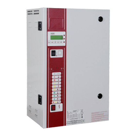
Fascia Label symbols Network Button Network LED (Service Pin) (Red) Cylinder 2 Cylinder 1 User LED1 User LED2 (If fitted) Red/Green/Amber Red/Amber/Green Unit Off Unit Off On-line On-line Standby Standby Drain Fault Drain Fault Feed Fault Feed Fault Over Over Current Current Service Interval... -
Page 20: Trouble-Shooting Check List
Ensure that the humidifier has an operational level of water in the cylinder. Switch unit on and check that the display indicates “Vapac on line”. Apply the voltmeter, set to the ful line Voltage, across the output terminals of the SSR being tested (i.e. -
Page 21: Wiring Diagram
AI 1 ref. AI 1 0 v DC + 5v DC Grey TO SHEET BLUE 2 of 3 VAPAC TWIN CYLINDER ELECTRO HUMIDIFIER CONTROL FITTED WITH VAPAC 1150630 motherboard Main supply N.T.S. for control , control transformer and customer control signal inputs... - Page 22 OF 67 & 68 and 69, 70. FAULT ALARM CUSTOMER CONNECTION TERMINALS CYLINDER 2 CYLINDER 1 DRAIN PUMP DRAIN PUMP 240 V 240 V VAPAC TWIN CYLINDER ELECTRO HUMIDIFIER CONTROL FITTED WITH VAPAC 1150630 motherboard N.T.S. control input for temp. and RH sensor or control pot...
- Page 23 LZD595 OR 596 NO NC C NO NC C NO NC C NO NC C 1 2 3 4 5 6 VAPAC TWIN CYLINDER ELECTR0 HUMIDIFIER CONTROL FITTED WITH VAPAC 1150630 motherboard N.T.S. control input for temp. and RH sensor...
- Page 24 TWIN CYLINDER UNIT LE60P High voltage cylinder 1 of unit Low voltage less than 380 High voltage is greater than or Equal to 380 volts VAPAC TWO or THREE ELECTRODE CYLINDERS POWER CONNECTION WIRING DIAGRAM FOR LEO5, LE05P, LE09, LE09P, LE18, N.T.S.
- Page 25 LE90P high voltage cyllinder 1 of unit Low voltage less than 380 High voltage is greater than or Equal to 380 volts VAPAC SIX ELECTRODE CYLINDEDR POWER CONNECTION WIRING DIAGRAME FOR LE30P LOW VOLTAGE AND LE45P HIGH VOLTAGE SINGLE N.T.S.
- Page 26 C1-1 Cylinder 2 2/3 Electrode E1 & E2 OR E1, E2 & E3 for twin cylinder units 3 Phase LEC05; LEC09 ; LEC18 & LEC30 HIGH VOLTAGE - CYLINDER 2 Neutral & Earth Supply"A" Low voltage less than 380 High voltage is greater than or...
- Page 27 TWIN CYLINDER UNITS LEC30 low voltage & LEC45 cyllinder 2 of unit Neutral & Earth Supply"A" Low voltage less than 380 High voltage is greater than or Equal to 380 volts VAPAC SIX ELECTRODE CYLINDEDR POWER CONNECTION WIRING DIAGRAME FOR LEC30 LOW VOLTAGE AND LEC45 - CYLINDER 2 N.T.S.
-
Page 28: A Guide To Positioning Steam Pipes
Appendix 1. A Guide to Positioning Steam Pipes: Vapac Humidity Control Ltd. Issue this as a guide only, and accept no responsibility for the positioning of any pipes in a system. This remains the responsibility of the Project Design Engineer. - Page 29 NB. The duct should be clear of obstructions, transformations and bends until the steam has been absorbed into the airflow. A guide to calculating this distance is available from W > 200 Vapac – Part Number 0411047. October 02 Fig 3 Fig 4...
-
Page 30: A Guide To Positioning Multipipes
Appendix 2 A Guide to Positioning Multipipes: Vapac Humidity Control Ltd. Issue this as a guide only, and accept no responsibility for the positioning of any pipes in a system. This remains the responsibility of the Project Design Engineer. Notes:... - Page 31 Made in England by: June 2004. Vapac Humidity Control Ltd. Vapac Humidty Control Ltd. reserve the right to change the design or specification of the equipment described in this manual without prior notice.
Need help?
Do you have a question about the LEC05 and is the answer not in the manual?
Questions and answers