Table of Contents
Advertisement
Service Literature
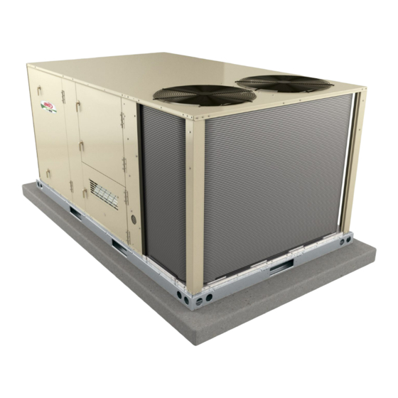
The LGH092H, 094U, 102H, 120H, 122U, 150S and
152U units are configure to order units (CTO) with a wide
selection of factory-installed options. Units are avail
able in 130,000, 180,000 Btuh or 240,000 Btuh (38.1,
52.7 or 70.3 kW) heating inputs. Gas heat sections are
designed with Lennox' aluminized steel tube heat ex
changers with stainless steel as an option.
Cooling capacities range from 7.5 to 12.5 tons (38.1 to
70.3 kW). All units are equipped with two compressors.
Ultra-high efficiency units are available with an optional di
rect drive blower or belt drive blower equipped with a sup
ply air inverter. Standard and high efficiency units are
available with a belt drive blower equipped with an option
al supply air inverter. The blower will operate at lower
speeds when demand is low and increase to higher
speeds when demand is high.
The following examples show the model numbers of ten-
ton units with all available blower options:
LGH120H4B
High Efficiency Belt Drive
LGH120H4M High Efficiency Belt Drive with Inverter
LGH122U4M Ultra High Efficiency Belt Drive with Inverter
LGH122U4E
Ultra High Efficiency Direct Drive
Note - Ten-ton units are available in high and ultra high effi
ciencies only.
Standard and high efficiency units come standard with a
lightweight, all-aluminum condenser coil; optional, fin/
tube condenser coils are available. Ultra-high efficiency
units come standard with a tube/fin condenser coil.
Ultra high efficiency units come standard with two single-
speed compressors plumbed in tandem to form a single re
frigerant circuit.
Units are also designed for R410A refrigerant. See unit
nameplate. Operating pressures and pressure switch set
tings are significantly higher than R22 charged units. Ser
vice equipment must be rated for R410A.
Standard and high efficiency units offer mechanical cooling
down to 0°F when properly equipped. Ultra-high efficiency
units offer mechanical cooling down to 40°F.
All LGH units are designed to accept any of several differ
ent energy management thermostat control systems with
minimum field wiring. Factory or field provided control op
tions connect to the unit with jack plugs. When "plugged in"
the controls become an integral part of the unit wiring.
Information contained in this manual is intended for use by
qualified service technicians only. All specifications are
subject to change. Procedures outlined in this manual are
presented as a recommendation only and do not super
sede or replace local or state codes.
Corp. 1008-L2
Revised 5/2015
LGH092H through 152U
If the unit must be lifted for service, rig unit by attaching four
cables to the holes located in the unit base rail (two holes at
each corner). Refer to the installation instructions for the
proper rigging technique.
Parts Arrangement
II-Placement and Installation
III-Charging
V-System Service Checks
VI-Maintenance
VII-Accessories
VIII-Belt Drive Supply Air Inverter
IX-Direct Drive Supply Air Blower
X-Staged Supply Air Operation
Improper installation, adjustment, alteration, service
or maintenance can cause property va, personal in
jury or loss of life. Installation and service must be
performed by a licensed professional HVAC installer
or equivalent, service agency, or the gas supplier
As with any mechanical equipment, contact with
sharp sheet metal edges can result in personal in
jury. Take care while handling this equipment and
wear gloves and protective clothing.
LGH SERIES
7.5 to 12.5 ton
38.1 to 70.3 kW
Table of Contents
. . . . . . . . . . . . . . . . . . . . .
. . . . . . . . . . . . . . . . . . . . . . . . . . . .
. . . . . . . . . . . . . . . . . . . . . . . . . . . .
. . . . . . . . . . . . . . . . . . . . . . . . . . .
. . . . . . . . . . . . . . . . . . . . . . .
. . . . . . . . . . . . . . . . . . . . . . .
. . . . . . . . . . . . . . .
. . . . . . . . . . . . . . . . . . . . . . . . . . . . . .
. . . . . . . . . . . . . . . . . . . .
. . . . . . . . . . . . . . . .
. . . . . . . . . . . . . . . . . . . . . . . . .
. . . . . . . . . . . . . . . . . . . . . . . . . .
. . . . . . . . . . . . . . . . . . . . . . . . . .
. . . . . . . . . . .
. . . . . . . . . . .
. . . . . . . . . . . . .
. . . . . . . . .
WARNING
CAUTION
Page 2
Page 8
Page 14
Page 19
Page 25
Page 28
Page 47
Page 47
Page 55
Page 57
Page 59
Page 59
Page 60
Page 67
Page 70
Page 71
Page 72
© 2015
Advertisement
Table of Contents

Related Manuals for Lennox LGH092H4B


Summary of Contents for Lennox LGH092H4B
- Page 1 130,000, 180,000 Btuh or 240,000 Btuh (38.1, proper rigging technique. 52.7 or 70.3 kW) heating inputs. Gas heat sections are designed with Lennox' aluminized steel tube heat ex changers with stainless steel as an option. Cooling capacities range from 7.5 to 12.5 tons (38.1 to 70.3 kW).
-
Page 2: Options / Accessories
OPTIONS / ACCESSORIES - 092H, 102H, 120H, 150S Unit Model No Model Catalog Item Description Number Number 092 102 120 COOLING SYSTEM Condensate Drain Trap PVC - C1TRAP20AD2 76W26 Copper - C1TRAP10AD2 76W27 Conventional Fin/Tube Condenser Coil (replaces all-aluminum coil) Factory Corrosion Protection Factory... - Page 3 OPTIONS / ACCESSORIES - 092H, 102H, 120H, 150S Unit Model No Model Catalog Item Description Number Number 092 102 120 CONTROLS 53W65 Blower Proving Switch C1SNSR35FF1 Commercial Controls L Connection Building Automation System - - - ® Prodigy Control System - BACnet Module - C0CTRL60AE1L 59W51 ®...
- Page 4 OPTIONS / ACCESSORIES - 092H, 102H, 120H, 150S Unit Model No Model Catalog Item Description Number Number 092 102 120 OUTDOOR AIR Outdoor Air Dampers With Outdoor Air Hood 63W60 Motorized E1DAMP20B-1 Manual C1DAMP10B-1 53W48 POWER EXHAUST Standard Static 208/230V-3ph - K1PWRE10B-1Y 53W44 460V-3ph - K1PWRE10B-1G 53W45...
- Page 5 OPTIONS / ACCESSORIES - 094U, 122U, 152U Unit Model No Model Catalog Item Description Number Number COOLING SYSTEM Condensate Drain Trap PVC - C1TRAP20AD2 76W26 Copper - C1TRAP10AD2 76W27 Corrosion Protection Factory Drain Pan Overflow Switch E1SNSR71AD1 68W88 Refrigerant Type R-410A HEATING SYSTEM Bottom Gas Piping Kit...
- Page 6 OPTIONS / ACCESSORIES - 094U, 122U, 152U Unit Model No Model Catalog Item Description Number Number CABINET Combination Coil/Hail Guards E1GARD51BP1 13T06 51W25 Horizontal Discharge Kit K1HECK00B-1 Return Air Adaptor Plate (for LC/LG and TC/TG/TH unit replacement) C1CONV10B-1 54W96 CONTROLS Blower Proving Switch C1SNSR35FF1 53W65...
- Page 7 OPTIONS / ACCESSORIES - 094U, 122U, 152U Unit Model No Model Catalog Item Description Number Number Standard Economizer E1ECON15B-1 55W05 Downflow or Horizontal - Includes Outdoor Air Hood and Downflow Barometric Relief Dampers with Exhaust Hood Order Horizontal Barometric Relief Dampers separately High Performance Economizer (Approved for California Title 24 Building Standards) High Performance Economizer E1ECON17B-1...
-
Page 8: Specifications
SPECIFICATIONS - 092H, 102H General Data Nominal Tonnage 7.5 Ton 7.5 Ton 8.5 Ton 8.5 Ton Model Number LGH092H4B LGH092H4M LGH102H4B LGH102H4M Efficiency Type High High High High Blower Type Constant Air (Multi-Stage Air Constant Air (Multi-Stage Air Volume CAV Volume) Volume CAV Volume) - Page 9 SPECIFICATIONS - 120H, 150S General Data Nominal Tonnage 10 Ton 10 Ton 12.5 Ton 12.5 Ton Model Number LGH120H4B LGH120H4M LGH150S4B LGH150S4M Efficiency Type High High Standard Standard Blower Type Constant Air Multi-Stage Air Constant Air Multi-Stage Air Volume CAV Volume Volume CAV Volume...
- Page 10 SPECIFICATIONS - GAS HEAT - 092H, 102H, 120H, 150S Heat Input Type Standard Medium High Number of Gas Heat Stages Gas Heating Input - Btuh First Stage 84,500 117,000 156,000 Performance Second Stage 130,000 180,000 240,000 Output - Btuh Second Stage 104,000 144,000 192,000...
- Page 11 SPECIFICATIONS - DIRECT DRIVE MODELS General Data Nominal Tonnage 7.5 Ton 10 Ton 12.5 Ton Model Number LGH094U4E LGH122U4E LGH152U4E Efficiency Type Ultra Ultra Ultra Blower Type Direct Drive Direct Drive Direct Drive Cooling Gross Cooling Capacity - Btuh 93,700 119,000 141,900 Performance...
- Page 12 SPECIFICATIONS - BELT DRIVE MODELS - 094U, 122U, 152U General Data Nominal Tonnage 7.5 Ton 10 Ton 12.5 Ton Model Number LGH094U4M LGH122U4M LGH152U4M Efficiency Type Ultra Ultra Ultra Blower Type Belt Drive Belt Drive Belt Drive Cooling Gross Cooling Capacity - Btuh 93,700 119,000 141,900...
- Page 13 SPECIFICATIONS - GAS HEAT - 094U, 122U, 152U Heat Input Type Standard Medium High Number of Gas Heat Stages Gas Heating Input - Btuh First Stage 84,500 117,000 156,000 Performance Second Stage 130,000 180,000 240,000 Output - Btuh Second Stage 104,000 144,000 192,000...
-
Page 14: Blower Tables
BLOWER DATA 092, 094, AND 102 BELT DRIVE BLOWER − BASE UNIT BLOWER TABLE INCLUDES RESISTANCE FOR BASE UNIT ONLY (NO HEAT SECTION) WITH DRY INDOOR COIL AND AIR FILTERS IN PLACE. FOR ALL UNITS ADD: 1 − Wet indoor coil air resistance of selected unit. 2 −... - Page 15 BLOWER DATA 120, 122, 150 AND 152 BELT DRIVE BLOWER − BASE UNIT BLOWER TABLE INCLUDES RESISTANCE FOR BASE UNIT ONLY (NO HEAT SECTION) WITH DRY INDOOR COIL AND AIR FILTERS IN PLACE. FOR ALL UNITS ADD: 1 − Wet indoor coil air resistance of selected unit. 2 −...
- Page 16 BLOWER DATA - 092, 094, 102, 120, 122, 150, 152 FACTORY INSTALLED BELT DRIVE KIT SPECIFICATIONS Motor Efficiency Nominal hp Maximum hp Drive Kit Number RPM Range Standard & High 590 - 890 Standard & High 800 - 1105 Standard & High 795 - 1195 Standard 3.45...
- Page 17 BLOWER DATA CEILING DIFFUSERS AIR RESISTANCE - in. w.g. RTD11 Step-Down Diffuser FD11 Flush Air Volume 1 Side, 2 Ends All Ends & Sides Diffuser Unit Size 2 Ends Open Open Open 2400 0.21 0.18 0.15 0.14 2600 0.24 0.21 0.18 0.17 2800...
- Page 18 BLOWER DATA - DIRECT DRIVE - 094U, 122U, 152U BLOWER TABLE INCLUDES RESISTANCE FOR BASE UNIT ONLY (NO HEAT SECTION) WITH DRY INDOOR COIL AND AIR FILTERS IN PLACE. FOR ALL UNITS ADD: 1 − Wet indoor coil air resistance of selected unit. 2 −...
-
Page 19: Electrical Data
ELECTRICAL DATA 7.5 TON HIGH EFFICIENCY (R-410A) LGH092H4 Voltage - 60hz 208/230V - 3 Ph 460V - 3 Ph 575V - 3 Ph Compressor 1 Rated Load Amps 13.1 Locked Rotor Amps 83.1 Compressor 2 Rated Load Amps 13.1 Locked Rotor Amps 83.1 Outdoor Fan Full Load Amps... - Page 20 ELECTRICAL DATA 10 TON HIGH EFFICIENCY (R-410A) LGH120H4 Voltage - 60hz 208/230V - 3 Ph 460V - 3 Ph 575V - 3 Ph Compressor 1 Rated Load Amps 13.5 Locked Rotor Amps Compressor 2 Rated Load Amps 13.5 Locked Rotor Amps Outdoor Fan Full Load Amps Motors (2)
- Page 21 ELECTRICAL DATA 7.5 TON DIRECT DRIVE LGH094U4E Voltage - 60hz 208/230V - 3 Ph 460V - 3 Ph 575V - 3 Ph Compressor 1 Rated Load Amps 13.1 Locked Rotor Amps 83.1 Compressor 2 Rated Load Amps 13.1 Locked Rotor Amps 83.1 Outdoor Fan Full Load Amps...
- Page 22 ELECTRICAL DATA 12.5 TON DIRECT DRIVE LGH152U4E Voltage - 60hz 208/230V - 3 Ph 460V - 3 Ph 575V - 3 Ph Compressor 1 Rated Load Amps 19.6 Locked Rotor Amps 66.1 55.3 Compressor 2 Rated Load Amps 19.6 Locked Rotor Amps 66.1 55.3 Outdoor Fan...
- Page 23 ELECTRICAL DATA 7.5 TON BELT DRIVE LGH094U4M Voltage - 60hz 208/230V - 3 Ph 460V - 3 Ph 575V - 3 Ph Compressor 1 Rated Load Amps 13.1 Locked Rotor Amps 83.1 Compressor 2 Rated Load Amps 13.1 Locked Rotor Amps 83.1 Outdoor Fan Full Load Amps...
- Page 24 ELECTRICAL DATA 7.5 TON BELT DRIVE LGH094U4M Voltage - 60hz 208/230V - 3 Ph 460V - 3 Ph 575V - 3 Ph Compressor 1 Rated Load Amps 13.1 Locked Rotor Amps 83.1 Compressor 2 Rated Load Amps 13.1 Locked Rotor Amps 83.1 Outdoor Fan Full Load Amps...
-
Page 25: Parts Arrangement
PARTS ARRANGEMENT - 092H, 102H, 120H, 150S ALL-ALUMINUM COIL SYSTEM BLOWER EVAPORATOR MOTOR CONDENSER COIL FANS CONDENSER UNIT COIL CONTROLLER BLOWER ECONOMIZER (OPTIONAL) DISCONNECT / CIRCUIT BREAKER (FACTORY OR FIELD INSTALLED OPTION) HINGED ACCESS PANEL (OPTIONAL) INVERTER COMBUSTION (OPTIONAL) AIR INDUCER GAS VALVE COMPRESSORS FILTERS... - Page 26 PARTS ARRANGEMENT - 094U, 122U, 152U FIN/TUBE COIL CONDENSER EVAPORATOR FANS COIL FILTERS (FOUR - 20 X 25 X 2”) CONDENSER COIL BLOWER BLOWER MOTOR THIS SIDE OF HOUSING UNIT (DIRECT DRIVE SHOWN) CONTROLLER COMBUSTION AIR INDUCER GAS VALVE COMPRESSORS CONDENSATE BURNERS DRAIN FIGURE 3...
- Page 27 CONTROL BOX PARTS ARRANGEMENT - ULTRA HIGH EFFICIENCY NON-CE UNITS K3 BLOWER CONTACTOR (BELT DRIVE BLOWERS, WITH INVERTER AND BYPASS OPTION) OR TB13 TERMINAL STRIP (BELT DRIVE BLOW ERS, WITH INVERTER, NO BYPASS OPTION T43 CONTROL CONTROL COMPRESSOR 2 AND DIRECT DRIVE BLOWERS) TRANSFORMER TRANSFORMER CONTACTOR...
-
Page 28: I-Unit Components
I-UNIT COMPONENTS 4-Outdoor Fan Capacitors C1, C2 (non-Ultra units) WARNING Fan capacitors C1 and C2 370V / 10 MFD capacitors are used to assist in the start up of condenser fans B4 and B5. Electric shock hazard. Can cause injury or death. - Page 29 9-Burner Controls A3 11-Blower Motor Overload Relay S42 Two hp high efficiency blower motors and M-volt unit blower A3 controls gas heat section burner controls. Burner con motors are equipped with an overload relay. High efficiency trols are factory set and are not adjustable. The control blower motors and M-volt unit blower motors manufactured makes three attempts at ignition and then locks out the sys...
- Page 30 SIEMENS OVERLOAD RELAY BLUE RESET BUTTON IN FACTORY‐SET AUTO MODE (Turn clockwise to H for manual reset) GREEN TRIP INDICATOR (Flush with surface -- not tripped; Above surface -- tripped) RED TEST BUTTON AMP ADJUSTMENT DIAL Adjust relay amp setting according to value given on the blower motor nameplate. Proper relay amp setting equals motor nameplate FLA X service factor of 1.15 X .95.
- Page 31 PLUMBING, COMPRESSOR AND REFRIGERANT CIRCUITS DETAIL (HIGH EFFICIENCY ALL-ALUMINUM OUTDOOR COIL) INDOOR COIL STAGE 2 DRIERS INDOOR COIL STAGE 1 OUTDOOR COIL STAGE 2 COMPRESSOR OUTDOOR COIL STAGE 1 COMPRESSOR S7 HIGH PRESSURE S4 HIGH SWITCH PRESSURE SWITCH S87 LOW PRESSURE S88 LOW SWITCH...
- Page 32 PLUMBING, COMPRESSOR AND REFRIGERANT CIRCUITS DETAIL (OPTIONAL STANDARD EFFICIENCY FIN/TUBE COIL) OUTDOOR COIL STAGE 1 INDOOR COIL STAGE 2 OUTDOOR INDOOR COIL COIL STAGE 2 STAGE 1 DRIERS COMPRESSOR COMPRESSOR S87 LOW PRESSURE S88 LOW SWITCH PRESSURE SWITCH SUCTION LINE DISCHARGE LINE DISCHARGE...
- Page 33 PLUMBING, COMPRESSOR AND REFRIGERANT CIRCUITS DETAIL (OPTIONAL ULTRA HIGH EFFICIENCY UNITS WITH FIN/TUBE COIL) LIQUID LINE LIQUID LINE DISCHARGE LINE DISCHARGE LINE INDOOR COIL DRIER OUTDOOR COILS COMPRESSOR (1 CIRCUIT) COMPRESSOR COMMON COMMON DISCHARGE LINE SUCTION LINE A185 PRESSURE COMPRESSOR 2 HIGH TRANSDUCER TEMPERATURE LIMIT LOW PRESSURE...
- Page 34 B-Cooling Components NOTE-Refer to the wiring diagram section for specific unit operation. Standard and high efficiency units use independent cooling If Interlink compressor replacement is necessary, call circuits consisting of separate compressors, condenser coils 1-800-453-6669. and evaporator coils. See figure 12 or 13. Ultra high efficien cy units use a common cooling circuit consisting of two IMPORTANT compressors in parallel, two condenser coils in parallel,...
- Page 35 4-Low Ambient Switches S11, S84 When suction pressure drops to 40 + 5 psig (276 ± 34 kPa), (indicating low pressure), the switch opens and the The low ambient switch is an auto‐reset SPST N.O. pres compressor(s) is(are) de-energized. The switch auto sure switch which allows mechanical cooling operation matically resets when pressure in the suction line rises to at low outdoor temperatures.
- Page 36 9-Freezestats S49 and S50 10-Temperature Sensors RT37 and RT38 Standard and high efficiency units are equipped with a low Ultra high efficiency units are equipped with a temperature temperature switch (freezestat) located on the return sensor (thermistor) located on the back of each compres bend of each evaporator coil.
- Page 37 STANDARD BLOWER ASSEMBLY TO INCREASE BELT TENSION SIDE VIEW 1- Loosen four bolts securing motor mounting base to frame. 2- Turn adjusting bolt to the right, or clockwise, to move the motor away from the blower housing. MOTOR ALLEN SCREW IMPORTANT - Gap between end of frame and motor mounting base should be equal at both ends, i.e.
- Page 38 DIRECT DRIVE BLOWER ASSEMBLY BLOWER HOUSING BLOWER MOTOR SECURED TO THIS SIDE OF HOUSING REMOVE TWO SCREWS ON EACH SIDE TO SLIDE BLOWER OUT OF UNIT INLET GRID FIGURE 18 C-Blower Compartment 1-Blower Wheels The blower compartment is located between the evapora Belt drive blowers are equipped with one 15 in.
- Page 39 the Unit Controller will energize the unit after five (default) Determining Unit Air Volume minutes. While line voltage is continually checked by the IMPORTANT - VFD units are factory-set to run the blower Unit Controller, the voltage phasing is not. If one or more at full speed when there is a blower (G) demand without a phases is interrupted, power to one or more transformers heating or cooling demand.
- Page 40 LOCATION OF STATIC PRESSURE READINGS INSTALLATIONS WITH DUCTWORK INSTALLATIONS WITH CEILING DIFFUSERS ROOFTOP UNIT ROOFTOP UNIT RETURN AIR READING LOCATION RETURN AIR READING RE RE LOCATION SUPPLY SUPPLY TURN TURN FIRST BRANCH OFF OF MAIN RUN MAIN DUCT RUN SUPPLY AIR SUPPLY AIR READING READING...
- Page 41 Check Belt Tension MEASURE BELT TENSION Overtensioning belts shortens belt and bearing life. Check belt tension as follows: 1- Measure span length X. See figure 21. 2- Apply perpendicular force to center of span (X) with enough pressure to deflect belt 1/64” for every inch of FORCE span length or 1.5mm per 100mm of span length.
- Page 42 D-GAS HEAT COMPONENTS Burner Ignition Control A3 See unit nameplate for all -1 model unit Btuh capacities. The ignition control is located in the heat section and is manu See SPECIFICATIONS tables or unit nameplate for factured by Johnson Controls. See table 3 for LED codes. TABLE 3 Btuh capacities in -2 model units.
- Page 43 Flame rectification sensing is used on all LGH units. Loss of HEAT EXCHANGER ASSEMBLY flame during a heating cycle is indicated by an absence of HEAT flame signal (0 microamps). If this happens, the control will EXCHANGER immediately restart the ignition sequence and then lock out TUBE if ignition is not gained after the third trial.
- Page 44 INSERT LOCATION - DIRECT DRIVE ONLY STANDARD HEAT (130,000BTUH) HIGH HEAT (180,000BTUH) Note - No inserts on medium heat. INSERTS (4) INSERTS (2) FIGURE 27 5-Primary High Temperature Limits S10 TYPICAL GAS BURNER ASSEMBLY S10 is the primary high temperature limit and is located on the BURNER SUPPORT CAP blower deck to the right of the blower housing.
- Page 45 6-Flame Roll-out Limit S47 4.81in. x 1.25in. (122mm x 32mm) blower wheel. The motor operates at 3200RPM and is equipped with auto‐reset over Flame roll-out limit S47 is a SPST N.C. high temperature load protection. Blower is supplied by various manufacturers. limit located as shown in figure 30.
- Page 46 TABLE 4 The spark electrode is connected to the ignition control by a 8 mm silicone‐insulated stranded high voltage wire. The GAS VALVE REGULATION FOR LGH UNITS Operating Pressure wire uses 1/4” (6.35 mm)female quick connect on the elec Maximum (outlet) Factory Setting trode end and female spark plug-type terminal on the igni...
-
Page 47: Ii-Placement And Installation
II-PLACEMENT AND INSTALLATION mizer disabled until system stabilizes (approximately five Make sure the unit is installed in accordance with the in minutes). Make sure all outdoor air dampers are closed. stallation instructions and all applicable codes. See ac 2- Check each system separately with all stages operat cessories section for conditions requiring use of the op... - Page 48 TABLE 6 LGH/LCH102H All-Aluminum Coil Normal Operating Pressures - TXV Outdoor Coil Entering Air Temperature 65 °F 75 °F 85 °F 95 °F 105 °F 115 °F Suct Disc Suct Disc Suct Disc Suct Disc Suct Disc Suct Disc (psig) (psig) (psig) (psig)
- Page 49 LGH/LCH092H All-Aluminum Coil Charging Curves Outdoor Temperature (°F) Circuit 1 Circuit 2 115° 105° 95° 85° 75° 65° Suction Pressure (psig) LGH/LCH102H All-Aluminum Coil Charging Curves Outdoor Temperature (°F) Circuit 1 Circuit 2 115° 105° 95° 85° 75° 65° Suction Pressure (psig) Page 49...
- Page 50 LGH/LCH120H All-Aluminum Coil Charging Curves Outdoor Temperature (°F) Circuit 1 Circuit 2 115° 105° 95° 85° 75° 65° Suction Pressure (psig) LGH/LCH150S All-Aluminum Coil Charging Curves Outdoor Temperature (°F) Circuit 1 115° Circuit 2 105° 95° 85° 75° 65° Suction Pressure (psig) Page 50...
- Page 51 B-Refrigerant Charge and Check - Fin/Tube Coil - TXV TABLE 10 LGH/LCH092H Fin/Tube Coil Hot Gas Reheat - TXV LGH/LCH092H, 102H, 120H, 150S CIRCUIT 1 CIRCUIT 2 WARNING-Do not exceed nameplate charge under any Outdoor Dis Dis Coil condition. charge Suction charge Suction...
- Page 52 TABLE 15 F-Refrigerant Charge and Check - Fin/Tube Coil & RFC LGH/LCH150S Fin/Tube Coil - TXV LGH/LCH150S CIRCUIT 1 CIRCUIT 2 Outdoor Dis Dis Coil WARNING-Do not exceed nameplate charge under any charge Suction charge Suction Entering condition. +5 psig +5 psig +10 psig +10 psig...
- Page 53 TABLE 18 LGH/LCH150S Normal Operating Pressures - Fin/Tube - RFC Outdoor Coil Entering Air Temperature 65 °F 75 °F 85 °F 95 °F 105 °F 115 °F Suct Disc Suct Disc Suct Disc Suct Disc Suct Disc Suct Disc (psig) (psig) (psig) (psig)
- Page 54 G-Refrigerant Charge and Check - Fin/Tube Coil & TXV TABLE 19 LGH/LCH094U LGH/LCH094U, 122U, 152U Outdoor Coil Discharge +10 Entering Air Suction +5 psig WARNING-Do not exceed nameplate charge under any psig Temp condition. 655 F This unit is factory charged and should require no further 755 F adjustment.
-
Page 55: Iv-Start Up - Operation
IV-START-UP - OPERATION REFRIGERANT CIRCUITS - Fin/Tube Coil Refer to start-up directions and to the unit wiring diagram (BOTH FANS ARE ENERGIZED when servicing. See unit nameplate for minimum circuit WITH A Y1 DEMAND) ampacity and maximum fuse size. EVAPORATOR A-Preliminary and Seasonal Checks COIL STAGE 2 1- Make sure the unit is installed in accordance with the... - Page 56 C-Heating Start-up 8- Close or replace the heat section access panel. 9- Turn on all electrical power to appliance. FOR YOUR SAFETY READ BEFORE LIGHTING 10- Set thermostat to desired setting. WARNING 11- The combustion air inducer will start. The burners will light within 40 seconds.
-
Page 57: V-System Service Checks
V- SYSTEMS SERVICE CHECKS result in permanent damage to the gas valve or “overfire.” For natural gas units, operating pressure at the unit gas A-Heating System Service Checks connection must be between 4.7”W.C. and 10.5”W.C. All LGH units are ETL/CSA design certified without mod (1168 Pa and 2610 Pa). - Page 58 5-Proper Gas Flow 8-Heat Exchanger To check for proper gas flow to burners, determine Btuh in To Access or Remove Heat Exchanger From Unit: put from unit rating plate or the gas heating capacity in the 1- Turn off gas and electric power. SPECIFICATIONS tables.
-
Page 59: High Altitude
10-Combustion Air Inducer WARNING The combustion air inducer is factory set and is not field ad justable. However, operation should be monitored to en Electric shock hazard. Can cause sure proper operation. The combustion air inducer is used injury or death. Before attempting to to draw fresh air into the combustion chamber while simul... -
Page 60: Vii-Accessories
VII-ACCESSORIES TYPICAL FLASHING DETAIL The accessories section describes the application of most of UNIT BASE BOTTOM the optional accessories which can be factory or field installed to the LGH units. UNIT BASE A-Mounting Frames RAIL When installing units on a combustible surface for downflow FIBERGLASS INSULATION discharge applications, a C1CURB roof mounting frame is... - Page 61 LAOAD(M) MOTORIZED OUTDOOR AIR DAMPER MOTORIZED DAMPER COVER PANEL HORIZONTAL SUPPLY AIR OPENING COMPRESSOR HORIZONTAL SECTION RETURN AIR OPENING LOWER PANEL FIGURE 42 MANUAL OUTDOOR AIR DAMPER COVER PANEL MANUAL DAMPER HORIZONTAL SUPPLY AIR OPENING COMPRESSOR HORIZONTAL SECTION RETURN AIR OPENING LOWER PANEL FIGURE 43...
- Page 62 ECONOMIZER ACCESSORY PANEL MULLION ECONOMIZER DIVIDER PANEL BOTTOM OF COMPRESSOR SECTION FLANGED RETURN AIR OPENING FIGURE 44 H-Economizer (all units) NOTE - All free cooling modes of operation will modu late dampers to 55_F (13_C) supply / discharge air. (Field or Factory Installed) The optional E1ECON15 economizer can be used with Unit Controller Settings downflow and horizontal air discharge applications.
- Page 63 SENSOR LOCATION FIN/TUBE UNIT SHOWN DISCHARGE AIR SENSOR RT16 RETURN AIR SENSOR RT17 OUTDOOR AIR SENSOR (ON RT17 ULTRA HIGH EFFICIENCY UNITS OUTDOOR AIR SENSOR (ON HIGH AND UNITS EQUIPPED WITH AN AND STANDARD EFFICIENCY UNITS ALL-ALUMINUM COIL; SECURED EQUIPPED WITH TUBE/FIN COIL) TO INSIDE OF CORNER MULLION) FIGURE 45 I-Gravity Exhaust Dampers...
- Page 64 K-Optional Cold Weather Kit (Canada only) L-Control Systems The A55 Unit Controller provides all control function for the Electric heater is available to automatically control the rooftop unit. Default operation requires a standard room minimum temperature in the gas burner compartment. thermostat or direct digital controller (DDC).
- Page 65 P-Factory Installed-Hot Gas Reheat (optional) valve, L14, routes hot discharge gas from the compressor to the reheat coil. Return air pulled across the evaporator General coil is cooled and dehumidified; the reheat coil adds heat to Hot Gas Reheat units provide a dehumidifying mode of op supply air.
- Page 66 1- Make sure reheat is wired as shown in wiring section. L14 Reheat Coil Solenoid Valve 2- Make sure unit is in local thermostat mode. When Unit Controller input (Unit Controller J298-5 or 3- Select Unit Controller Service - Test. J299-8) indicates room conditions require dehumidifi...
-
Page 67: Viii-Belt Drive Supply Air Inverter
VIII-Belt Drive Supply Air Inverter Use figure 50 to determine whether the VFD should be pro viding a staged output to the blower motor. The supply air inverter or variable frequency drive (VFD), is located in the compressor compartment. The VFD stages the amount of supply airflow according to the number of com... - Page 68 ADJUST CFM Measure the intake air CFM. If the CFM is lower than the design specified CFM for ventilation air, use the Unit Con If a test and balance contractor has not commissioned the troller to increase the damper percent open. If the CFM is unit, use this section to set supply air CFM.
- Page 69 TABLE 27 MINIMUM AND MAXIMUM CFM 092H, 102H, 120H, 150S Gas Heat Minimum CFM Unit Gas Heat Size Airflow CFM LGH092-150 Std. , Med. 2225 LGH092-150 High 2550 Electric Heat Minimum CFM Unit Heat Size (kW) Airflow CFM LCH092-102 2800 LCH092-150 7.5, 15, 22.5, 30, 45 2800...
- Page 70 IX-Direct Drive Supply Air Inverter B-Set Damper Minimum Position To maintain required minimum ventilation air volumes when If a test and balance contractor has not commissioned the the unit is in the occupied mode, two minimum damper posi unit, use this section to set supply air CFM. tions must be set.
-
Page 71: X-Staged Supply Air Operation
TABLE 29 X-Staged Supply Air Operation MINIMUM AND MAXIMUM CFM This is a summary of cooling operation for both belt and di 094U4E, 122U4E, 152U4E rect drive blowers. Gas Heat Minimum CFM Note - During a dehumidification demand the blower oper Unit Gas Heat Size Airflow CFM*... - Page 72 XI-Wiring Diagrams and Sequence of Operation LGH092/150S & H - CONSTANT SUPPLY AIR, BELT DRIVE BLOWER Page 72...
- Page 73 LGH092/150S & H SEQUENCE OF OPERATION Power: 1- Line voltage through the S48 unit disconnect, TB2 terminal block, or CB10 circuit breaker energizes the T1 trans former. T1 provides 24VAC power to A55 Unit Controller which provides 24VAC to the unit cooling, heating and blower controls.
- Page 74 LGH092/152U STAGED SUPPLY AIR, NO BYPASS, BELT DRIVE BLOWER Page 74...
- Page 75 LGH092/152U M3 SEQUENCE OF OPERATION Power: 1- Line voltage through the S48 unit disconnect, TB2 terminal block, or CB10 circuit breaker energizes the T1 trans former. T1 provides 24VAC power to A55 Unit Controller which provides 24VAC to the unit cooling, heating and blower controls.
- Page 76 GAS HEAT FOR LGH092/150 UNITS Page 76...
- Page 77 GAS HEAT SEQUENCE OF OPERATION LGH092/150 First Stage Heat: End of Second Stage Heat: 1- Heating demand initiates at W1 in the thermostat. 9- Heating demand is satisfied. Terminal W2 (high fire) is 2- 24VAC is routed through TB34 to the A55 Unit Con de-energized.
- Page 78 ELECTRONIC OR ELECTROMECHANICAL THERMOSTAT POWER: The A55 Unit Controller energizes the thermostat components with 24VAC via J/P297-1. OPERATION: The A55 Unit Controller proves the optional N.O. filter switch S27 (indicates dirty filter when closed) and optional N.O. air flow switch S52 (indicates no air [i.e. broken belt] system shuts down). The A55 Unit Controller receives data from the supply and return smoke detectors A171 and A172, blower motor overload relay S42, discharge sensor RT6 and return air sensor RT16.
- Page 79 BRWN DESCRIPTION A130 COMPONENT TB37 SENSOR, SOLID STATE ENTHALPY CONTROL, ERS A130 CONTROL, MAIN PANEL LENNOX SENSOR, ENTHALPY INDOOR CONTROL, REMOTE MIN POS (OPT) MOTOR, DAMPER ECONOMIZER MOTOR, EXHAUST DAMPER JACK, UNIT ECONOMIZER JACK, SENSOR OUTDOOR ENTHALPY J104 JACK, SENSOR RETURN AIR ENTHALPY...
- Page 80 LGH/LCH092-150S & H STAGED SUPPLY AIR, NO BYPASS, BELT DRIVE BLOWER Page 80...
- Page 81 LGH/LCH092-150S & H STAGED SUPPLY AIR, WITH BYPASS, BELT DRIVE BLOWER Page 81...
- Page 82 LGH/LCH092-152U STAGED SUPPLY AIR, WITH BYPASS, BELT DRIVE BLOWER Page 82...
- Page 83 SUPPLY AIR INVERTER - NO BYPASS SEQUENCE OF OPERATION OPERATION: A96 FAULT SEQUENCE: A55 energizes the K203 relay coil. A96 will interrupt the 0-10VDC signal at terminal 2 on an in ternal failure. A96 will retry three times before terminals B-C K203-2 N.O.
- Page 84 LGH/LCH092-152U STAGED SUPPLY AIR, DIRECT DRIVE BLOWER Direct Drive EBM Blower Motor: The blower speed is deter mined by thermostat demand and settings programmed into the A55. When A55 receives a Y1 demand, a low speed volt age output from A55 terminal 4 will energize B3 in low speed. When A55 receives a Y2 demand, a high speed voltage output from A55 terminal 4 will energize B3 in high speed.
- Page 85 DIRECT DRIVE BLOWER SEQUENCE OF OPERATION / TROUBLESHOOTING Blower Operation: Line voltage is routed to B3 blower motor through TB2 terminal strip, TB13 terminal strip, T4 transformer (575v units only), and J/P48 terminals 1, 2 and 3. B3 blower motor runs internal diagnostics to check for proper temperature, voltage, etc. (KL2-2 and -3). This process takes approximately 10 seconds.
- Page 86 TABLE 30 DIRECT DRIVE BLOWER MOTOR TROUBLESHOOTING Failure Error Warning Reason Troubleshoot No changes in hall signals Check for obstruction keeping Locked Rotor • within 2000ms impeller from rotating Warning, no error code set, Check for secondary airflow source in Braking Mode •...
Need help?
Do you have a question about the LGH092H4B and is the answer not in the manual?
Questions and answers