Table of Contents
Advertisement
Quick Links
S e r v i c e L i t e r a t u r e
WARNING
To prevent serious injury or death:
1- Lock-out/tag-out before performing maintenance.
2- If system power is required (e.g., smoke detector
maintenance), disable power to blower, remove
fan belt where applicable, and ensure all
controllers and thermostats are set to the "OFF"
position before performing maintenance.
3- Always keep hands, hair, clothing, jewelry, tools,
etc., away from moving parts.
WARNING
Electric shock hazard. Can cause injury
or death. Before attempting to perform
any service or maintenance, turn the
electrical power to unit OFF at disconnect
switch(es). Unit may have multiple power
supplies.
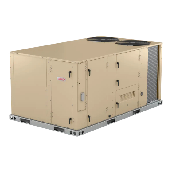
The LDT commercial combination heat pump and gas
heat unit is available in 6.5 / 7.5 / 8.5 / 10 / 12.5 ton cool-
ing capacities. The LDT078, 092, 102, 122 and 150 re-
frigerant systems utilize two compressors, two reversing
valves, two accumulators (122, 150 only), and other parts
common to a heat pump. Units are available in 130,000,
180,000 or 240,000Btuh (38.1, 52.7 or 70.3 kW) heating
inputs. Gas heat sections are designed with stainless
steel tube heat exchangers.
LDT078-150 units are equipped with variable-volume, di-
rect drive blowers. These units will provide supply air at
lower speeds when cooling demand is low and increase
to higher speeds when cooling demand is high. Refer to
Supply Air Start-Up sections.
LDT units are designed to accept any of several different
energy management thermostat control systems with min-
imum field wiring.
Information contained in this manual is intended for use
by qualified service technicians only. All specifications are
subject to change. Procedures outlined in this manual are
presented as a recommendation only and do not super-
sede or replace local or state codes.
If the unit must be lifted for service, rig unit by attaching
four cables to the holes located in the unit base rail (two
holes at each corner). Refer to the installation instructions
for the proper rigging technique.
UNIT INFORMATION
UNIT INFORMATION
100086
LDT DUAL FUEL SERIES
Page 1
6.5 / 7.5 / 8.5 / 10 / 12.5
WARNING
Improper
installation,
service or maintenance can cause property damage,
personal injury or loss of life. Installation and service
must be performed by a licensed professional HVAC
installer or equivalent, service agency, or the gas
supplier
CAUTION
As with any mechanical equipment, contact with
sharp sheet metal edges can result in personal
injury. Take care while handling this equipment and
wear gloves and protective clothing.
Table of Contents
Options / Accessories . . . . . . . . . . . . . . . . . . . . . Page 2
Specifications . . . . . . . . . . . . . . . . . . . . . . . . . . . . Page 5
Blower Tables . . . . . . . . . . . . . . . . . . . . . . . . . . . Page 8
Electrical Data . . . . . . . . . . . . . . . . . . . . . . . . . . Page 11
I-Unit Components . . . . . . . . . . . . . . . . . . . . . . . Page 14
II-Placement and Installation . . . . . . . . . . . . . . . Page 27
III-Start Up . . . . . . . . . . . . . . . . . . . . . . . . . . . . . . Page 27
IV-System Service Checks. . . . . . . . . . . . . . . . . . . . Page 30
V-Maintenance . . . . . . . . . . . . . . . . . . . . . . . . . . Page 33
VII-Wiring and Operation Sequence . . . . . . . . . . Page 39
LDT
adjustment,
alteration,
Advertisement
Table of Contents

Related Manuals for Lennox LDT DUAL FUEL Series


Summary of Contents for Lennox LDT DUAL FUEL Series
-
Page 1: Table Of Contents
6.5 / 7.5 / 8.5 / 10 / 12.5 100086 S e r v i c e L i t e r a t u r e LDT DUAL FUEL SERIES WARNING To prevent serious injury or death: 1- Lock-out/tag-out before performing maintenance. -
Page 2: Options / Accessories
OPT IONS / A C C ESSORIES Unit Model No Catalog Item Description Number 078 092 102 122 150 COOLING SYSTEM Condensate Drain Trap 22H54 Copper 76W27 Drain Pan Overflow Switch 21Z07 GAS HEATING SYSTEM 54W95 Bottom Gas Piping Kit Combustion Air Intake Extensions 19W51 Gas Heat Input... - Page 3 OPT IONS / A C C ESSORIES Unit Model No Catalog Item Description Number 078 092 102 122 150 INDOOR AIR QUALITY Air Filters Healthy Climate High Efficiency Air Filters MERV 8 50W61 ® 20 x 25 x 2 in. (Order 4 per unit) MERV 13 52W41 MERV 16...
- Page 4 OPT IONS / A C C ESSORIES Unit Model No Catalog Item Description Number 078 092 102 122 150 ECONOMIZER High Performance Economizer (Approved for California Title 24 Building Standards / AMCA Class 1A Certified) High Performance Economizer 20U80 Downflow or Horizontal - Includes Outdoor Air Hood and Downflow Barometric Relief Dampers with Exhaust Hood Order Horizontal Barometric Relief Dampers separately Horizontal Barometric Relief Dampers...
-
Page 5: Specifications
SP ECIF ICATIONS 6.5 TO N | 7 .5 TO N | 8.5 TO N General Data Nominal Tonnage 6.5 Ton 7.5 Ton 8.5 Ton Efficiency Type High High High Model Number LDT078H4E LDT092H4E LDT102H4E Blower Type DirectPlus™ DirectPlus™ DirectPlus™ ECM Direct Drive ECM Direct Drive ECM Direct Drive... - Page 6 SP ECIF ICATIONS 10 TO N | 1 2 . 5 TO N General Data Nominal Tonnage 10 Ton 12.5 Ton Efficiency Type High High Model Number LDT122H4E LDT150H4E Blower Type DirectPlus™ DirectPlus™ ECM Direct Drive ECM Direct Drive with MSAV® with MSAV®...
- Page 7 SP ECIF ICATIONS GA S HEAT Heat Input Type Standard Medium High Number of Gas Heat Stages Gas Heating Input - Btuh First Stage 84,500 117,000 156,000 Performance Second Stage 130,000 180,000 240,000 Output - Btuh Second Stage 104,000 144,000 194,000 Temperature Rise Range - °F 15 - 45...
-
Page 8: Blower Tables
B LOWER D ATA BLOWER TABLE INCLUDES RESISTANCE FOR BASE UNIT ONLY (NO HEAT SECTION) WITH DRY INDOOR COIL AND AIR FILTERS IN PLACE. FOR ALL UNITS ADD: 1 − Wet indoor coil air resistance of selected unit. 2 − Any factory installed options air resistance (heat section, Economizer, etc.) 3 −... - Page 9 BLO WER DATA FACTORY INSTALLED OPTIONS/FIELD INSTALLED ACCESSORY AIR RESISTANCE - in. w.g. Wet Indoor Coil Gas Heat Exchanger Filters Return Volume Economizer Standard Medium High Adaptor 092, 102 MERV 8 MERV 13 MERV 16 Heat Heat Heat Plate 1750 0.04 0.04 0.06...
- Page 10 BLO WER DATA CEILING DIFFUSERS AIR RESISTANCE - in. w.g. RTD11 Step-Down Diffuser FD11 Flush Air Volume 1 Side, 2 Ends All Ends & Sides Diffuser Unit Size 2 Ends Open Open Open 2400 0.21 0.18 0.15 0.14 2600 0.24 0.21 0.18 0.17...
-
Page 11: Electrical Data
ELECTRIC AL DATA 6 .5 TO N Model No. LDT078H4E Voltage - 60Hz 208/230V-3ph 460V-3ph 575V-3ph Compressor 1 Rated Load Amps 12.9 (Non-Inverter) Locked Rotor Amps Compressor 2 Rated Load Amps (Non-Inverter) Locked Rotor Amps Outdoor Fan Full Load Amps (2 ECM) Motors (2) Total Power Exhaust... - Page 12 ELECTRIC AL DATA 8 .5 TO N Model No. LDT102H4E Voltage - 60Hz 208/230V-3ph 460V-3ph 575V-3ph Compressor 1 Rated Load Amps 12.9 (Non-Inverter) Locked Rotor Amps Compressor 2 Rated Load Amps (Non-Inverter) Locked Rotor Amps 38.9 Outdoor Fan Full Load Amps (2 ECM) Motors (2) Total Power Exhaust...
- Page 13 LDT078-150 PARTS ARRANGEMENT INDOOR BLOWER OUTDOOR FANS COIL (DIRECT DRIVE) (3 ON 122 & 150) FILTERS (FOUR - 20 X 25 X 2”) ECONOMIZER (OPTIONAL) WIFI ANTENNA UNIT CONTROLLER COMBUSTION WIRELESS AIR INDUCER BOARD GAS VALVE COMPRESSORS BURNERS CONDENSATE REVERSING DRAIN VALVE FIGURE 1...
-
Page 14: I-Unit Components
I-UNIT COMPONENTS 208/230V TRANSFORMER WARNING BLUE YELLOW SECONDARY Electric shock hazard. Can cause injury or death. Before attempting to perform any service or maintenance, turn the 208 VOLTS electrical power to unit OFF at disconnect switch(es). Unit may have multiple power 230 VOLTS supplies. - Page 15 PLUMBING COMPONENTS LDT078-102 Condenser Coil Evaporator Coil Reversing Valve Reversing Valve Compressor 2 Compressor 1 LDT122-150 Condenser Coil Evaporator Coil Reversing Valve Accumulators Compressor 1 Compressor 2 FIGURE 4 Page 15...
- Page 16 B-Cooling Components 2-Freezestats S49 and S50 LDT units use independent cooling circuits consisting of Each unit is equipped with a low temperature switch separate compressors, outdoor coils and indoor coil (with (freezestat) located on the return bend of each indoor coil. 2 separate stages).
- Page 17 5-Reversing Valve L1 and L2 8-Filter Drier (all units) A refrigerant reversing valve with a 24 volt solenoid coil is LDT units have a filter drier located in the liquid line of used to reverse refrigerant flow during unit operation in all each refrigerant circuit at the exit of each condenser coil LDT units.
- Page 18 LDT078, 092, 102, 122, 150 INDOOR COIL RT46, RT47 Lorem ipsum 22J06 BLUE RT47 22J06 YELLOW RT46 DETAILS NOT TO SCALE FIGURE 5 Page 18...
- Page 19 LDT078, 092, 102, 122, 150 OUTDOOR COIL RT48, RT49 22J08 BLUE RT49 22J08 YELLOW RT48 DETAILS NOT TO SCALE FIGURE 6 Page 19...
- Page 20 C-Blower Compartment NOTE - Blower operation mode can also be initiated by the mobile service app. The blower compartment in all LDT078-150H units is lo- Direct-drive motor may not immediately stop when power cated between the indoor coil and the outdoor coil section. is interrupted to the Unit Controller.
- Page 21 LOCATION OF STATIC PRESSURE READINGS INSTALLATIONS WITH DUCTWORK INSTALLATIONS WITH CEILING DIFFUSERS ROOFTOP UNIT ROOFTOP UNIT RETURN AIR READING LOCATION RETURN AIR READING LOCATION SUPPLY SUPPLY TURN TURN FIRST BRANCH OFF OF MAIN RUN MAIN DUCT RUN SUPPLY AIR SUPPLY AIR READING READING DIFFUSER...
- Page 22 TABLE 1 DIRECT DRIVE PARAMETER SETTINGS - 581102-01 Field Parameter Description Setting Note: Any changes to Smoke CFM setting must be adjusted before the other CFM settings. Use SETTINGS > RTU OPTIONS > EDIT PARAMETERS = 12 for EBM, 6 for ECM BLOWER SMOKE CFM % Percentage of RPM for blower smoke speed.
- Page 23 D-GAS HEAT COMPONENTS 2-Gas Heat Exchanger Inserts (Some LDT Units) 1-Heat Exchanger FIGURE 9 Inserts are installed on standard (130,000Btuh) heat ex- changers in tubes one and three. Medium and high heat exchangers do not require inserts. See FIGURE 10. In- HEAT EXCHANGER ASSEMBLY serts are used to maintain even temperature distribution HEAT...
- Page 24 Orifice 6-Combustion Air Prove Switch S18 Each burner uses an orifice which is precisely matched Prove switch S18 is a SPST N.O. switch located to the to the burner input. Install only the orifices with the right of the induced draft assembly. S18 monitors com- same threads.
- Page 25 9-Gas Valves GV1 Spark gap may be checked with appropriately sized twist drills or feeler gauges. Disconnect power to the unit and Gas valve GV1 is a two-stage redundant valve.. On first remove electrode assembly. The gap should be between stage (low fire) is quick opening (on and off in less than 3 0.125”...
- Page 26 12-Burner Control A3 TABLE 4 LED Flashes Indicates WARNING Slow Flash Control ok, no call for heat Shock hazard. Spark related components Fast Flash Control ok, call for heat present. contain high voltage which can cause Steady Off Internal control fault or no power personal injury or death.
-
Page 27: Ii-Placement And Installation
IGNITION CONTROL TIMING END OF 6 (+3.4, -2.0) SEC. THERMOSTAT DEMAND SECONDS 0 HEATING CYCLE THERMOSTAT DEMAND COMBUSTION AIR BLOWER GAS VALVE IGNITION SPARK BLOWER IGNITION TRIAL 42 SEC. 122 SEC. FIGURE 16 Flame rectification sensing is used on all units. Loss of II-PLACEMENT AND INSTALLATION flame during a heating cycle is indicated by an absence of Make sure the unit is installed in accordance with the in-... - Page 28 1 - Set thermostat or temperature control device to WARNING initiate a first-stage heating demand. A first-stage heating demand (W1) will energize compres- Danger of explosion. Can cause injury or sors 1 and 2. All outdoor fans are energized with a W1 death.
- Page 29 Three Phase Scroll Compressor Voltage Phasing WHITE RODGERS 36H54 GAS VALVE Three phase power supplied to the unit disconnect switch Two-Stage must be phased sequentially to ensure the scroll com- pressor and indoor blower rotate in the correct direction. Compressor and blower are wired in phase at the factory. Power wires are color-coded as follows: line 1-red, line 2-yellow, line 3-blue.
-
Page 30: Iv-System Service Checks
IV- SYSTEMS SERVICE CHECKS TABLE 5 WARNING LDT078 - 581118-01 CIRCUIT 1 CIRCUIT 1 Outdoor Refrigerant can be harmful if it is inhaled. Refrigerant Coil Dis- Suction Discharge Suction must be used and recovered responsibly. Entering charge +5 psig +10 psig +5 psig Air Temp ⁰... - Page 31 TABLE 9 GAS PIPING COMPONENTS REFER TO INSTALLATION INSTRUCTIONS LDT150 - 581122-01 CIRCUIT 1 CIRCUIT 1 VALVE Outdoor GROUND JOINT UNION Coil Dis- Dis- Suction Suction Entering charge charge +5 psig +5 psig MANUAL MAIN Air Temp ⁰ F +10 psig +10 psig SHUT-OFF VALVE CAP HERE...
- Page 32 4-Check and Adjust Manifold Pressure 6-Heat Exchanger After line pressure has been checked and adjusted, check To Access or Remove Heat Exchanger From Unit: manifold pressure. Move test gauge to the outlet pressure 1 - Turn off gas and electric power. tap located on unit gas valve GV1.
-
Page 33: V-Maintenance
VI-MAINTENANCE D-Indoor Coil Inspect and clean coil at beginning of each cooling and WARNING heating season. Clean using mild detergent or commer- cial coil cleanser. Flush coil and condensate drain with Electric shock hazard. Can cause injury water taking care not to get insulation, filters and return or death. -
Page 34: Vi-Accessories
VII-ACCESSORIES TYPICAL FLASHING DETAIL UNIT BASE The accessories section describes the application of most BOTTOM of the optional accessories which can be factory or field installed to the LDT units. UNIT BASE RAIL A-C1CURB Mounting Frames FIBERGLASS INSULATION When installing the LDT units on a combustible surface (Furnished) for downflow discharge applications, the C1CURB roof mounting frame is used. - Page 35 C1DAMP20B-1 MOTORIZED OUTDOOR AIR DAMPER MOTORIZED DAMPER COVER PANEL HORIZONTAL SUPPLY AIR OPENING COMPRESSOR HORIZONTAL SECTION RETURN AIR OPENING LOWER PANEL C1DAMP10B-2 MANUAL OUTDOOR AIR DAMPER COVER PANEL MANUAL DAMPER HORIZONTAL SUPPLY AIR OPENING COMPRESSOR HORIZONTAL SECTION RETURN AIR OPENING LOWER PANEL FIGURE 25 Page 35...
- Page 36 ECONOMIZER ACCESSORY PANEL MULLION ECONOMIZER DIVIDER PANEL BOTTOM OF COMPRESSOR SECTION FLANGED RETURN AIR OPENING FIGURE 26 TABLE 12 ECONOMIZER MODES AND SETPOINT Free Cooling Free Cooling Field Provided Dampers will modulate to 55°F (default, parameter 159) discharge Input Ranges Mode Set Point Sensors...
- Page 37 E-K1ECON20B Economizer BAROMETRIC RELIEF DAMPERS - DOWNFLOW (Field- or Factory-Installed) The optional E1ECON15 economizer can be used with downflow and horizontal air discharge applications. See FIGURE 26. The economizer uses outdoor air for free cooling when outdoor temperature and/or humidity is suit- able.
- Page 38 K-LP / Propane Kit A6 ENTHALPY CONTROLLER Units require a natural to LP /propane kit. The kit includes one LP spring conversion kit, up to eleven burner orifices and three stickers. For more detail refer to the natural to ADJUST POWER EXHAUST FAN LP gas changeover kit installation instructions.
-
Page 39: Vii-Wiring And Operation Sequence
X-Wiring Diagrams and Sequence of Operation GAS HEAT Y and G Voltage MODBUS A55.P393 MAIN CTRL 1 3 2 J413 J393 P413 P393 LOW TEMP VEST HTR BURNER 1 LTVH−1 MODBUS CABLE P229 FROM LTVH−2 P411 P406 P229 J411 J406 1 3 2 A G B DSI CTRL 1... - Page 40 GAS HEAT FOR J Voltage MODBUS A55.P393 MAIN CTRL J413 J393 P413 P393 LOW TEMP VEST HTR BURNER 1 LTVH−1 MODBUS CABLE P229 FROM LTVH−2 P411 P406 J411 J406 A G B DSI CTRL 1 MODBUS−1 J407 J410 P407 P410 DRNWR MODBUS CABLE J408...
- Page 41 GAS HEAT SEQUENCE OF OPERATION LDT078H-150H First Stage Heat: End of Second Stage Heat: 1 - Heating demand initiates at W1 in the thermostat. 8 - Heating demand is satisfied. Terminal W2 (high fire) is de-energized. 2 - 24VAC is routed through the A55 unit controller to A3 Ignition Control.
- Page 42 ELECTRONIC OR ELECTROMECHANICAL THERMOSTAT − 0 1 A173 CTRL SMOKE DETECT J250 P250 P251 J251 J252 P252 P253 J253 FIRE ALARM CONTACT SUPPLIED BY OTHERS FROM IAQ WIRING DIAGRAM DI−1 P299 P387 J299 J387 MAIN CTRL J297 J298 P297 P298 J387 J298 J297 J299 IAQ+...
- Page 43 ECONOMIZER MS7110K RANGE 2−10 VDC NF24−SR AF24−SR RANGE 2−10 VDC P104 P105 RT16 J104 J105 P384 J384 MAIN CTRL Model: LC, LG, LH, LD Series RTU HTG CLG ACCS ACCS Economizer & Motorized OAD WI R I N G DI AGRAM F LOW Voltage: All Voltages 538072−01...
- Page 44 Y Voltage With Higher SCCR DRNWR TO A3 ON GAS UNITS. REF A−SECT LOC CC01−02 RED−BLK RED−BLK 24VAC RT17 SHIELDED CABLE HPSW1 TWISTED PAIR HTSW1 DRNWR RED−BLK RED−BLK 24VAC ODF1 RT48 RT46 PWM2 P336 HTSW2 P337 RED−BLK 24VAC RED−BLK RT49 RT47 OPTIONAL IONIZER ODF2...
- Page 45 G Voltage With Higher SCCR DRNWR TO A3 ON GAS UNITS. REF A−SECT LOC CC01−02 RED−BLK RED−BLK 24VAC RT17 SHIELDED CABLE HPSW1 TWISTED PAIR HTSW1 DRNWR RED−BLK RED−BLK 24VAC ODF1 RT48 RT46 PWM2 P336 HTSW2 P337 RED−BLK RED−BLK 24VAC RT49 RT47 OPTIONAL IONIZER ODF2...
- Page 46 J Voltage With Higher SCCR DRNWR TO A3 ON GAS UNITS. REF A−SECT LOC CC01−02 RED−BLK RED−BLK 24VAC RT17 SHIELDED CABLE HPSW1 TWISTED PAIR HTSW1 DRNWR RED−BLK RED−BLK 24VAC ODF1 RT48 RT46 PWM2 P337 HTSW2 P336 RED−BLK RED−BLK 24VAC RT49 RT47 OPTIONAL IONIZER ODF2...
- Page 47 LDT078-150H SEQUENCE OF OPERATION Power: 1 - Line voltage through the S48 unit disconnect, TB2 terminal block, or CB10 circuit breaker energizes the T1 transformer. T1 provides 24VAC power to A55 Unit Controller which provides 24VAC to the unit cooling, heating and blower controls. 2 - Line voltage is also routed to compressor crankcase heaters, compressor contactors, the blower motor, condenser fan relays and exhaust fan relays.
- Page 48 SEQUENCE OF OPERATION LDT078-150 (continued) First Stage Heat - OD Temp BELOW Balance Point (35°F Default) Outdoor Ambient Temperature W1 Demand W2 Demand 5 - Unit controller A55 receives W1 demand. If the OD air temperature is Above Balance Point Compr.
- Page 49 DIRECT DRIVE BLOWER SEQUENCE OF OPERATION / TROUBLESHOOTING Blower Operation: 1 - Line voltage is routed to B3 blower motor through TB2 terminal strip, TB13 terminal strip and J/P48 terminals 1, 2 and 3. 2 - B3 blower motor runs internal diagnostics to check for proper temperature, voltage, etc. (KL2-2 and -3). This process takes approximately 10 seconds. Refer to the Failure Handling/Troubleshooting section.
- Page 50 TABLE 13 DIRECT DRIVE BLOWER MOTOR TROUBLESHOOTING Failure Error Warning Reason Troubleshoot No changes in hall signals within Locked Rotor Check for obstruction keeping impeller from rotating 2000ms Warning, no error code set, Motor Check for secondary airflow source in the system causing the Braking Mode start not possible after 20 sec impeller to rotate backwards when off...
Need help?
Do you have a question about the LDT DUAL FUEL Series and is the answer not in the manual?
Questions and answers