
Related Manuals for LEGRAND 0 766 42


Summarization of Contents
DESCRIPTION OF THE SYSTEM ARCHITECTURE
Fundamental Installation Rules
Essential guidelines for safe and correct installation of the Mosaic nurse call system.
Wiring Principle Diagram
Explains the basic wiring configuration of the nurse call system components and their connections.
Ward Installation Principles
Details the system installation layout for wards, covering different room configurations.
DECT Call Forwarding & Traceability
Describes system setup for call forwarding and traceability using DECT and telephone coupling.
Equipment Selection Guide
Guide for selecting appropriate equipment based on room requirements and system design.
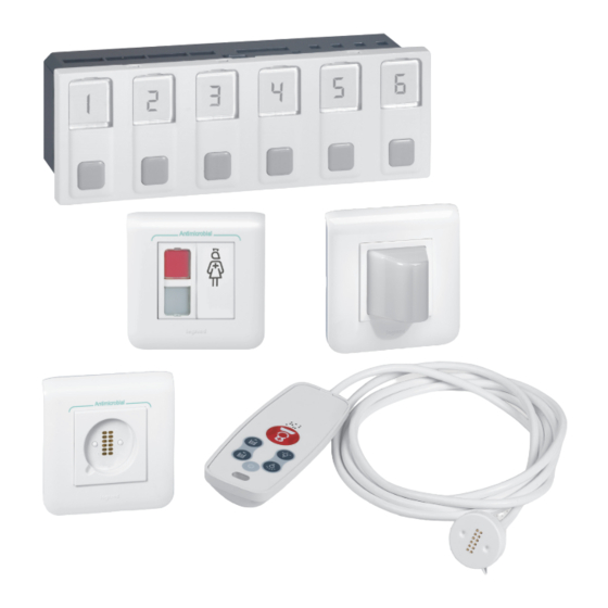
PRESENTATION AND INSTALLATION OF DEVICES
6-Direction Call Display Unit
Details the 6-direction call display unit, its functions, and technical specifications.
3-Direction Management Module
Describes the 3-direction management module, its capabilities, and connections.
Table Control Unit
Information on the table control unit, a support frame for display units.
Power Supply Units
Details the power supply units required for the system operation.
Door Unit
Explains the door unit, its indicators, push-button, and installation methods.
Bathroom Call Units & Buttons
Describes bathroom call units/buttons, their features, and installation.
Corded Push-Button Sockets & Buttons
Details sockets and buttons for corded push-buttons and their technical specifications.
Hand-Held Remote Control Sockets
Information on sockets for mounting hand-held remote control units.
Hand-Held Remote Control Units
Describes hand-held remote control units for patient calls and other functions.
Remote Control Modules for SELV Functions
Details remote control modules for SELV functions like lighting and roller blinds.
Bathroom Call Pull-Cord Unit
Describes the bathroom call unit with a pull-cord and LED indicator.
Corridor Indicator Lights
Details the double indicator light for corridors showing calls and nurse presence.
Corridor Call Transfer & Buzzers
Describes units for transferring calls to the corridor and audible alerts.
Biomedical Call Plug & Socket
Information on a plug and socket for connecting medical devices and signaling alarms.
OPERATING MODE
Call and Nurse Presence
Explains the operational sequence for patient calls and nurse presence.
Bathroom Call and Nurse Presence
Details the operation for bathroom calls and nurse presence, including priority.
Emergency Nurse Assistance
Describes the procedure for emergency calls and nurse response.
Nurse Presence with Inter-Room Calls
Explains how nurse presence and calls from different rooms are handled.
Nurse Presence with Inter-Bathroom Calls
Details nurse presence and calls originating from bathrooms.
NURSE CALL UNIT WIRING MOSAIC
Wiring: Nursing Homes & Elderly Care
Wiring diagram for typical installations in nursing and elderly care facilities.
Wiring: Remote Controls & Magnetic Sockets
Wiring diagram for installations using hand-held remote controls and magnetic sockets.
Wiring: Push-Button with Indicator
Wiring diagram for installations using push-buttons with indicator and information transfer.
Wiring: Bed & Armchair Calls
Wiring diagram for bed/armchair calls and presence in nursing/elderly homes.
Wiring: DECT Interface Integration
Wiring diagram showing DECT interface integration for traceability.
Wiring: Clinics, Hospitals & Corridor Displays
Wiring diagram for clinics/hospitals with biomedical calls and corridor displays.
Wiring: Patient Call & IP Network Cabling
Wiring diagram for patient call, corridor units, and IP network cabling.
COMMISSIONING
Pre-Switch-On Checks
Steps to perform pre-checks before powering on the installed system.
Module Reset Procedure
Instructions for resetting system modules to their default state.
TROUBLESHOOTING
Door Unit Fault Diagnosis
Identifies issues related to the door unit based on indicator light behavior.
Corded Push-Button Fault
Identifies issues related to faulty corded push-buttons.
Biomedical/Bathroom Pull-Cord Fault
Identifies issues with biomedical alarms or bathroom pull-cords.
Management Module Damage
Indicates potential damage to the management module based on indicator status.
Magnetic Socket Polarity Issue
Identifies incorrect polarity in magnetic sockets for hand-held units.
Need help?
Do you have a question about the 0 766 42 and is the answer not in the manual?
Questions and answers