Table of Contents
Advertisement
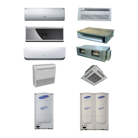
AIR CONDITIONER
Refer to the service manual in the GSPN(see the rear cover) for the more information.
SYSTEM AIR CONDITIONER
INDOOR UNIT
AVXCSH022/028/036EE
ND022/028/0361HXEA/XSE
AVXC2H056/071EE
AVXC4H045/056/071/090/112/128/140EE
AVXC4H045/056/071/090/112/128/140EG
ND045/056/071/090/112/128/1404HXEA/XSE
AVXCMH028/036/056/060EE
AVXDSH022/028/036/045/056/071/090/112/128/140EE
ND022/028/036/045/056/071/090/112/128/140LHXEA
ND022/028/036/045/056/071/090/112/128/140LHXEA/XSE
AVXDUH056/071/090/112/128/140EE
ND056/071/090/112/128/140SHXEA/XSE
ND140HHXEA
AVXDUH210/280EG
ND200/220/280HHXEA
ND200/220/280HHXEA/XSE
ND220/280HHXEASTK
AVXTFH056/071EE
ND056/071CHXEA/XSE
AVXTJH028/036/056EE
ND028/036/056JHXEA/XSE
AVXWBH028/036/056/071EE
ND028/036/056/071BHXEA/XSE
AVXWNH022/028/036/056/071EE
ND022/028/036/056/071NHXEA/XSE
ND022/028/036/045/056/071QHXEA
AVXWVH022/028/036/056/071EE
ND022/028/036/056/071VHXEA/XSE
ND0561/0711HXEH
ND022/028/036/045/056/071QHXEB
ND022/028/036/045/056/071QHXEBSTK
1. Precautions
2. Product Specifications
3. Disassembly and Reassembly
4. Troubleshooting
5. Exploded Views and Parts List
6. PCB Diagram and Parts List
7. Wiring Diagram
8. Schematic Diagram
9. Reference Sheet
OUTDOOR UNIT
RD080/100/120/140/160/180/200HHXGA
RD080/100/120/140/160/180/200HRXGA
RD080/100/120/140/160/180/200HHXGB
RD080/100/120/140/160/180/200HRXGB
RD080/100/120/140/160/180/200 HHXGASTK
RD080/100/120/140/160/180/200 HHXGASTK
RD080/100/120/140/160/180/200HHXGBXSE
CONTENTS
Advertisement
Table of Contents

Related Manuals for Samsung RD200HHXGB


Summarization of Contents
Precautions
Precautions for the Service
Guidelines for handling electrical parts, connections, and general repair practices for safety and product integrity.
Precautions for the Static Electricity and PL
Handling PCB terminals and components carefully to prevent damage from static electricity and ensure proper installation.
Precautions for the Safety
Essential safety measures including handling power plugs, wires, and grounding to prevent electrical hazards.
Precautions for Handling Refrigerant for Air Conditioner
Environmental and safety considerations for handling refrigerants, including prevention of gas release and frostbite.
Precautions for Welding the Air Conditioner Pipe
Safety guidelines for welding pipes, emphasizing removal of flammable objects and use of nitrogen gas.
Precautions for Additional Supplement of Air Conditioner Refrigerant
Guidelines for accurately calculating and supplementing refrigerant to prevent product damage.
Other Precautions
Important precautions regarding pipe leakage, compressor operation, and air entry into the refrigerant cycle.
Product Specifications
The Feature of Product
Detailed features of the product, including world-class COP, core technology, and installation advantages.
Product Specifacations
Comprehensive specifications for indoor units, including performance, dimensions, functions, and accessories.
Accessory and Option Specifications
Lists and details of available accessories and optional components for the air conditioning system.
Disassembly and Reassembly
Necessary Tools
List of essential tools required for the disassembly and reassembly procedures of the indoor unit.
Indoor Unit
Step-by-step procedures for disassembling and reassembling various parts of the indoor unit.
Outdoor Unit
Detailed procedures for disassembling and reassembling the outdoor unit components.
MCU
Disassembly and reassembly procedures specifically for the MCU (Multi Control Unit).
EEV KIT
Procedures for disassembling and reassembling the EEV (Electronic Expansion Valve) kit.
Troubleshooting
Check-up Window Description
Explanation of the check-up window and its functions for troubleshooting the outdoor unit.
Troubleshooting
Detailed troubleshooting steps for various operational issues, including setting option codes.
Diagnosis Checklist
Guidance on diagnosing problems based on numerical displays and error codes.
Auto Inspect Mode
Procedures and guidelines for using the auto inspect mode to identify system abnormalities.
Responses According to Condition
Troubleshooting steps for specific conditions, including sensor errors and communication issues.
Exploded Views and Parts List
Indoor Unit
Exploded views and detailed parts lists for various types of indoor units.
Outdoor Unit
Exploded views and detailed parts lists for outdoor units across different models.
PCB Diagram and Parts List
Indoor Unit
Detailed PCB diagrams and parts lists for various indoor unit types.
Outdoor Unit
Detailed PCB diagrams and parts lists for outdoor units.
Parts List
Comprehensive lists of parts for various PCB assemblies, including MCU and sensor boards.
Wiring Diagram
Indoor
Wiring diagrams for various types of indoor units, illustrating connections between components.
Outdoor Unit
Wiring diagrams for outdoor units, detailing connections for HP and HR modes.
Schematic Diagram
Indoor Unit
Schematic diagrams for various indoor unit types, showing circuit functionalities.
Outdoor Unit
Schematic diagrams for outdoor unit PCBs, illustrating main board and hub connections.
Reference Sheet
Index for Model Name
Reference tables for decoding model names based on classification, design, mode, and specifications.
Refrigerant Circuit Diagram
Diagrams illustrating the refrigerant circuit and cycle operation modes for DVM PLUS 4 systems.
Pump-down Method
Procedures for refrigerant pump-down in single and multi-outdoor unit installations.
How to Put Refrigerant in Refrigerant Container
Step-by-step instructions for safely putting refrigerant into a container before pump-down.
Need help?
Do you have a question about the RD200HHXGB and is the answer not in the manual?
Questions and answers