Table of Contents
Advertisement
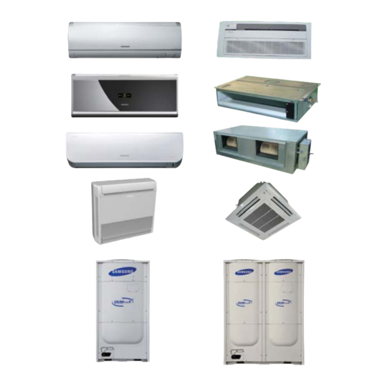
AIR CONDITIONER
Refer to the service manual in the GSPN(see the rear cover) for the more information.
SYSTEM AIR CONDITIONER
INDOOR UNIT
AVXCSH022/028/036EE
ND022/028/0361HXEA/XSE
AVXC2H056/071EE
AVXC4H045/056/071/090/112/128/140EE
AVXC4H045/056/071/090/112/128/140EG
ND045/056/071/090/112/128/1404HXEA/XSE
AVXCMH028/036/056/060EE
AVXDSH022/028/036/045/056/071/090/112/128/140EE
ND022/028/036/045/056/071/090/112/128/140LHXEA
ND022/028/036/045/056/071/090/112/128/140LHXEA/XSE
AVXDUH056/071/090/112/128/140EE
ND056/071/090/112/128/140SHXEA/XSE
ND140HHXEA
AVXDUH210/280EG
ND200/220/280HHXEA
ND200/220/280HHXEA/XSE
ND220/280HHXEASTK
AVXTFH056/071EE
ND056/071CHXEA/XSE
AVXTJH028/036/056EE
ND028/036/056JHXEA/XSE
AVXWBH028/036/056/071EE
ND028/036/056/071BHXEA/XSE
AVXWNH022/028/036/056/071EE
ND022/028/036/056/071NHXEA/XSE
ND022/028/036/045/056/071QHXEA
AVXWVH022/028/036/056/071EE
ND022/028/036/056/071VHXEA/XSE
ND0561/0711HXEH
ND022/028/036/045/056/071QHXEB
ND022/028/036/045/056/071QHXEBSTK
1. Precautions
2. Product Specifications
3. Disassembly and Reassembly
4. Troubleshooting
5. Exploded Views and Parts List
6. PCB Diagram and Parts List
7. Wiring Diagram
8. Schematic Diagram
9. Reference Sheet
OUTDOOR UNIT
RD080/100/120/140/160/180/200HHXGA
RD080/100/120/140/160/180/200HRXGA
RD080/100/120/140/160/180/200HHXGB
RD080/100/120/140/160/180/200HRXGB
RD080/100/120/140/160/180/200 HHXGASTK
RD080/100/120/140/160/180/200 HHXGASTK
RD080/100/120/140/160/180/200HHXGBXSE
CONTENTS
Advertisement
Table of Contents

Related Manuals for Samsung RD160HHXGB


Summarization of Contents
1. Precautions
1-1 Precautions for the Service
Guidelines for handling electric parts, connections, and general maintenance procedures.
1-2 Precautions for the Static Electricity and PL
Handling of PCBs, static prevention, and avoiding damage from electronic appliances.
1-3 Precautions for the Safety
Safety guidelines for handling power plugs, wiring, and grounding to prevent electric shock.
1-4 Precautions for Handling Refrigerant for Air Conditioner
Environmental and safety cautions regarding refrigerant release, suffocation, and noxious gas production.
1-5 Precautions for Welding the Air Conditioner Pipe
Safety measures before welding, including refrigerant removal and using nitrogen gas.
1-6 Precautions for Additional Supplement of Air Conditioner Refrigerant
Precise calculation of refrigerant, avoiding heating containers, and safety when removing pressure switches.
1-7 Other Precautions
No leakage after installation, proper pipe connection, and avoiding air/substance entry into the system.
2. Product Specifications
2-1 The Feature of Product
Details on world-class efficiency, core technology, and installation advantages of the DVM PLUS 4.
2-1-1 Feature
Highlights the world-class COP and low-temperature heating ability of the product.
2-1-2 Changes in comparison to basic model
Compares changes in FAN, Heat Exchanger, CABINET, Window Display, and MOTOR from basic models.
2-2 Product Specifacations
Detailed specifications for indoor units, including power, performance, sound level, and accessories.
2-2-1 Indoor Unit
Specifications for various indoor unit types, including Slim 1way cassette.
2 way cassette type
Detailed specifications for the 2-way cassette type indoor unit.
4 way cassette
Detailed specifications for the 4-way cassette type indoor unit.
2-1-5 Duct type(Slim I)
Specifications for the Slim I duct type indoor unit.
2-1-6 Duct type(Slim II)
Specifications for the Slim II duct type indoor unit.
2-1-7 Duct type(Slim III)
Specifications for the Slim III duct type indoor unit.
2-1-8 Duct type(MSP)
Specifications for the MSP duct type indoor unit.
2-1-9 Duct type(SUPER)
Specifications for the SUPER duct type indoor unit.
2-1-10 Duct type(BIG)
Specifications for the BIG duct type indoor unit.
2-1-11 Ceiling type
Specifications for the ceiling type indoor unit.
2-1-12 Wall Mounted type(Montblanc)
Specifications for the Montblanc wall-mounted indoor unit.
2-1-13 Wall-mounted type(Neo Forte without EEV)
Specifications for the Neo Forte wall-mounted indoor unit without EEV.
2-1-14 Wall-mounted type(Neo Forte with EEV)
Specifications for the Neo Forte wall-mounted indoor unit with EEV.
2-1-15 Wall-mounted type(Vivace)
Specifications for the Vivace wall-mounted indoor unit.
2-2-1 Outdoor Unit
Specifications for outdoor units, including models RD080HHXGA, RD100HHXGA, RD120HHXGA.
2-2-2 Outdoor Unit
Detailed specifications for outdoor units, including models RD140HHXG, RD160HHXG, etc.
3. Disassembly and Reassembly
3-1 Indoor Unit
Step-by-step procedures for disassembling and reassembling indoor units, including cassette types.
Slim 1 way cassette type (ND0561/0711HXE✳ Series)
Disassembly and reassembly of Slim 1 way cassette type indoor units.
3-1 BIG DUCT
Disassembly and reassembly procedures for BIG DUCT type units.
3-2 Outdoor Unit
Procedures for disassembling and reassembling outdoor units, including models RD080/100/120HHXG.
3-3 MCU
Procedures for disassembling and reassembling the MCU (Mode Control Unit).
3-4 EEV KIT
Procedures for disassembling and reassembling the EEV kit, including cabinet and control parts.
4. Troubleshooting
4-1 Check-up Window Description
Description of the outdoor unit's check-up window and its functions.
4-2 Troubleshooting
General troubleshooting procedures and methods.
4-2-1 Setting Option Setup Method
Steps for inputting PCB option codes using the wireless remote controller.
4-2-1-1 PCB option code input method
Detailed steps for inputting specific PCB option codes via remote controller.
4-2-1-2 Option Items
Table listing option items and their corresponding SEG values for various indoor unit models.
4-2-2 What to check before diagnosis
Checks to perform before diagnosing issues, including LED lamp displays.
4-2-2-1 Lamp combination expression method display (cassette type indoor unit)
Explains LED lamp displays for error detection and restart procedures for Slim 1 way and 2 way cassette types.
4-way, mini 4 way cassette type
Explains LED lamp displays for error detection and restart procedures for 4 way and mini 4 way cassette types.
Global 4way cassette type
Explains LED lamp displays for error detection and restart procedures for global 4-way cassette types.
Duct type
Explains LED lamp displays for error detection and restart procedures for duct type indoor units.
Ceiling type
Explains LED lamp displays for error detection and restart procedures for ceiling type indoor units.
Console type
Explains LED lamp displays for error detection and restart procedures for console type indoor units.
Wall-mounted type (Neo Forte without EEV/with EEV)
Explains LED lamp displays for error detection and restart for Neo Forte wall-mounted indoor units.
Wall-mounted type (Vivace/Montblanc)
Explains LED lamp displays for error detection and restart for Vivace/Montblanc wall-mounted indoor units.
4-3 Diagnosis Checklist
Checklist for diagnosing problems based on error code display methods.
4-3-1 Number Display Method (Outdoor Unit, MCU, Cable remote control, wall-mount, etc.)
Explains the meaning of error codes displayed on outdoor units, MCUs, and wall-mounted units.
4-4 Auto Inspect Mode
Identifies abnormalities in DVM PLUS IV components and provides guidelines for problem-solving.
4-4-1 Outline
Overview of the auto inspect mode and its safety function.
4-4-2 Auto Inspect Mode Steps
Details the procedure for accessing and performing auto inspect mode on the outdoor unit.
4-4-3 Preliminary Inspection
Lists inspection items and procedures before running the auto inspect mode.
4-4-4 Troubleshooting for inspected items
Provides a flowchart for diagnosing and troubleshooting issues identified during auto inspection.
Indoor unit air temperature and Eva.In/Out temperature sensors auto inspect
Procedure for inspecting indoor unit temperature sensors and their resistance values.
Pressure sensor auto inspect
Steps for auto inspecting pressure sensors, including checking service valve and refrigerant status.
Service Valve Auto Inspect
Procedure for inspecting service valve lock, 4-WAY VALVE, and MAIN EEV for proper operation.
Compressor Operation Auto Inspect
Steps for automatically inspecting compressor operation, power cable, CT sensor, and PWM valve.
Cycle State Auto Inspect
Evaluates cycle operation, including valve types, sensor function, and refrigerant status.
PWM Valve Auto Inspect
Procedure for inspecting PWM valve connectivity, coil, PBA output, and coil resistance.
Oil gas/Hot gas/Liquid Valve Auto Inspect
Steps for inspecting oil/hot gas/liquid valves for function, connector, coil, PBA, and pipe temperature changes.
4-Way Valve Auto Inspect
Procedure for inspecting the 4-way valve for function, connector, coil, PBA, and address settings.
EVI EEV Auto Inspect
Procedure for inspecting EVI EEV for connector, coil, resistance, and temperature sensor.
Main EEV Auto Inspect
Procedure for inspecting the Main EEV for function, connector, coil resistance, and overall normal operation.
4-4-5 Error Code
List of error codes and their corresponding descriptions for indoor units.
Error display order
Table detailing error modes, causes, measures, and product operation status during errors.
4-5 Responses According to Condition
Responses and actions for various operational conditions and errors.
4-5-1 Outdoor Unit Operation Flow
Flowchart illustrating the outdoor unit's operation sequence, including power, phase checks, and heating.
Reversed Phase/No Phase Check (Outdoor Unit with 3 Phase power) – Display E425 for Problem
Troubleshooting steps for reversed or no phase power issues in 3-phase compressor systems.
Initial Tracking (Communication Check-up) - Display E201 for Problem
Diagnosing communication errors between outdoor and indoor units based on display patterns.
Compressor Pretreatment display
Explanation of the 'Ch' display indicating compressor temperature and preheating status before operation.
4-5-2 Indoor Unit ROOM sensor Error (Open/Short)
Troubleshooting steps for ROOM sensor errors, including connector checks and resistance measurements.
4-5-3 Indoor unit EVAP IN sensor Error (Open/Short)
Troubleshooting steps for EVAP IN sensor errors, including connector checks and resistance measurements.
4-5-4 Indoor EVAP OUT sensor Error (Open/Short)
Troubleshooting steps for EVAP OUT sensor errors, including connector checks and resistance measurements.
4-5-5 Indoor Heat Exchanger's EVAP IN sensor dislocation error
Diagnosing EVAP IN sensor dislocation errors based on temperature and pressure readings during cooling and heating.
4-5-6 Indoor Heat Exchanger's EVA OUT sensor dislocation error (Open/Short)
Diagnosing EVA OUT sensor dislocation errors based on temperature and pressure readings during cooling and heating.
4-5-7 Simultaneous Indoor Heat Exchanger's EVA IN, OUT sensor dislocation error (Open/Short)
Diagnosing simultaneous EVA IN and OUT sensor dislocation errors based on temperature and pressure readings.
4-5-8 Operational error of indoor Unit's Clean Fan (Open/Short)
Troubleshooting steps for indoor unit fan motor operational errors, including checking connectors and capacitors.
4-5-9 Breakdown of EEV (2nd)
Diagnosing EEV breakdown during cooling operation, including wire connection and coil resistance checks.
4-5-10 Problem with EEV closure (2nd)
Troubleshooting EEV closure issues, checking wires, coils, and operating conditions.
4-5-11 : Detection of Floating Switch of Indoor Unit's Drain Pump
Diagnosing drain pump floating switch errors, including checking resistance, water level, and pump operation.
4-5-12 The operational error of Indoor Unit's Fan Motor
Troubleshooting operational errors of the indoor unit fan motor, checking HALL IC, capacitor, and motor status.
4-5-13 Mixed operation Error (Only applicable to Heat Pump Model/Not to HR model)
Addresses mixed operation errors that occur when indoor unit modes differ from current operational status.
4-5-14 EEPROM error
Troubleshooting EEPROM errors, checking for communication failure between EEPROM and MICOM.
4-5-15 Option error of the Remote Controller for an Indoor Unit
Resolving option errors related to missed or erroneous remote controller inputs.
4-5-16 Error due to confused use of Fahrenheit and Celsius
Troubleshooting errors caused by incorrect Fahrenheit/Celsius setting, particularly in Celsius-based models.
4-5-17 Simultaneous opening of Cooling/heating MCU SOL Valves 1st/2nd
Troubleshooting simultaneous opening errors of MCU SOL valves by checking connector and coil connections.
4-5-18 Error due to incorrect Indoor Unit Power/Communication Cable Connection
Diagnosing errors caused by incorrect indoor unit power or communication cable connections.
4-5-19 SPI Feedback Error
Troubleshooting SPI feedback errors by checking connector, measuring voltage, and replacing SPI or PCB.
4-5-20 Outdoor Unit Pipe Inspection Error
Diagnosing outdoor unit pipe inspection errors related to EVA IN/OUT changes.
4-5-21 Communication Error between Indoor and Outdoor Units during Tracking
Troubleshooting communication errors during tracking, checking unit installation quantity and PCB addresses.
4-5-22 Communication Error between Indoor and Outdoor Units after Tracking
Diagnosing communication errors after tracking, checking PCB address settings and communication cables.
4-5-23 Communication error between main and sub Micom of outdoor unit or between outdoor units
Troubleshooting communication errors between outdoor unit Micoms or between outdoor units.
4-5-24 Communication Error between MCU and Outdoor Unit
Troubleshooting communication errors between MCU and outdoor unit, checking address settings and cables.
4-5-25 Communication Error between MAIN/HUB PBA
Diagnosing communication errors between MAIN PBA and HUB PBA.
4-5-26 Communication Error between MCU and Outdoor Unit after Tracking is Completed
Troubleshooting communication errors between MCU and outdoor unit after tracking is completed.
4-5-27 MCU branch part setup error – inconsecutive connection with the use of 2 branch parts
Addressing MCU branch part setup errors when 2 branch parts are used consecutively.
4-5-28 MCU branch part setup error – Repeated setup for the same address over 3 times
Troubleshooting MCU branch part setup errors for repeated indoor unit address setup.
4-5-29 MCU branch part setup error – non-installed address setup
Addressing MCU branch part setup errors when an indoor unit is not installed but has an assigned address.
4-5-30 Setup Error for MCU Branch part – Setup Error for MCU Quantity Used
Troubleshooting setup errors for MCU branch parts related to the quantity of MCUs used or address overlaps.
4-5-31 MCU branch part setup error – Overlapping Indoor unit Address setup
Addressing MCU branch part setup errors when indoor unit addresses are overlapped in the setup switch.
4-5-32 MCU branch part setup error – Set as being used without connection to an Indoor unit
Troubleshooting MCU branch part setup errors where a part is used without being connected to an indoor unit.
4-5-33 MCU branch part setup error – Connect an Indoor unit to a branch part not being used
Addressing MCU branch part setup errors when connecting an indoor unit to an unused branch part.
4-5-34 MCU branch part setup error – Connect more Indoor units than what is actually set up in MCU
Troubleshooting MCU branch part setup errors when the number of connected indoor units exceeds the MCU setup.
4-5-35 Outdoor Temperature Sensor Error
Troubleshooting outdoor temperature sensor errors, checking connector and resistance values.
4-5-36 Outdoor Temperature dislocation error
Diagnosing outdoor temperature sensor dislocation errors by checking connector and resistance values.
4-5-37 COND OUT Temperature Sensor Error (OPEN/SHORT)
Troubleshooting COND OUT temperature sensor errors by checking connector and resistance values.
4-5-38 Outdoor COND OUT sensor breakaway error
Diagnosing outdoor COND OUT sensor breakaway errors by checking sensor attachment and resistance.
4-5-39 Digital Compressor Discharge Temperature Sensor Error (OPEN/SHORT)
Troubleshooting digital compressor discharge temperature sensor errors by checking connector and resistance values.
4-5-40 Constant Rate Compressor Discharge Temperature Sensor Error (OPEN/SHORT)
Troubleshooting constant rate compressor discharge temperature sensor errors by checking connector and resistance values.
4-5-41 Compressor Discharge Temperature Sensor Breakaway Error
Troubleshooting compressor discharge temperature sensor breakaway errors by checking attachment and operating conditions.
4-5-42 : Dislocation error of Compressor SUMP Temperature (oil temperature) Sensor
Diagnosing compressor sump temperature sensor dislocation errors by checking sensor attachment and comparing readings.
4-5-43 : Suction Temperature Sensor Breakaway Error
Troubleshooting suction temperature sensor breakaway errors by checking connector, resistance, and attachment.
4-5-44 SUMP Temperature Sensor Error (OPEN/SHORT)
Troubleshooting sump temperature sensor errors by checking connector and resistance values.
4-5-45 High Pressure Sensor Error (OPEN/SHORT)
Troubleshooting high pressure sensor errors by checking connector, voltage, refrigerant, and PCB.
4-5-46 Low-Pressure Sensor Error (OPEN/SHORT)
Troubleshooting low pressure sensor errors by checking connector, voltage, refrigerant, and PCB.
4-5-47 Oil balance temperature sensor error (OPEN/SHORT)
Troubleshooting oil balance temperature sensor errors by checking connector, resistance, and PCB.
4-5-48 Suction temperature sensor error (OPEN/SHORT)
Troubleshooting suction temperature sensor errors by checking connector, resistance, and PCB.
4-5-49 Double-pipe temperature sensor error (OPEN/SHORT)
Troubleshooting double-pipe temperature sensor errors by checking connector, resistance, and PCB.
4-5-50 Main Cooling Sol Valve Open Error
Troubleshooting main cooling solenoid valve errors by checking connector, coil, and operating sound.
4-5-51 EVI IN Temperature Sensor Error (OPEN/SHORT)
Troubleshooting EVI IN temperature sensor errors by checking connector, resistance, and PCB.
4-5-52 EVI OUT Temperature Sensor Error (OPEN/SHORT)
Troubleshooting EVI OUT temperature sensor errors by checking connector, resistance, and PCB.
4-5-53 Suction-2 Temperature Sensor Error (OPEN/SHORT)
Troubleshooting suction-2 temperature sensor errors by checking connector, resistance, and PCB.
4-5-54 : COMP. DOWN Due to High Pressure Protection Control
Diagnosing compressor down errors due to high pressure protection, checking valves, sensors, and refrigerant.
4-5-55 : COMP. DOWN Due to Low Pressure Protection
Diagnosing compressor down errors due to low pressure protection, checking valves, sensors, and refrigerant.
4-5-56 Sump Sensor Error Due to Protection Control
Troubleshooting sump sensor errors due to protection control, checking sensor connection and display.
4-5-57 : COMP.DOWN Due to Compressor Discharge Temperature Sensor
Diagnosing compressor down errors due to discharge temperature sensor, checking resistance, valves, and refrigerant.
4-5-58 3-phase Power Reversed Phase and No-phase Inspection
Troubleshooting 3-phase power issues by checking voltage, cable connection, and PCB.
4-5-59 : COMP. DOWN Due to Compressor Control
Diagnosing compressor down errors due to compressor control, checking valves, sensors, and pipe clogs.
4-5-60 : Oil Valve (oil balance valve) 1 Self-diagnosis (Open/Close error, Breakaway or Fault of Sensor)
Diagnosing oil balance valve errors, including sensor breakaway, temperature rise, and coil resistance.
4-5-61 EVI EEV Open Error
Troubleshooting EVI EEV open errors by checking connector, coil, leakage, and super cooler.
4-5-62 Refrigerant Leakage Error
Diagnosing refrigerant leakage errors by checking pressure sensors, connectors, and refrigerant levels.
4-5-63 , : Prohibition of the operation of Compressor due to OoutdoorTemperature
Addressing compressor operation prohibition due to outdoor temperature limits for heating and refrigerant filling.
4-5-64 High Pressure Standard Not Met before Air Conditioning (Inability to Re-operate)
Troubleshooting high pressure standard errors that prevent air conditioning or re-operation.
4-5-65 CCH Malfunction and Sump Sensor Miswiring Error
Diagnosing CCH malfunction and sump sensor miswiring errors by checking connections and resistance.
4-5-66 Momentary Blackout Error
Troubleshooting momentary blackout errors related to compressor stop.
4-5-67 Error by High Temperature in an Outdoor Fan Motor
Diagnosing outdoor fan motor errors due to high temperature, checking rotation and lock status.
4-5-68 Outdoor Unit Fan Motor RPM Error
Troubleshooting outdoor unit fan motor RPM errors by checking connector and PBA.
4-5-69 Over-Voltage Error of an Outdoor Fan Motor
Addressing over-voltage errors in outdoor fan motors by checking rotation and load status.
4-5-70 Counter-Rotation Error of an Outdoor Fan Motor
Troubleshooting counter-rotation errors in outdoor fan motors by checking start instruction and wind effects.
4-5-71 : Compressor Excess Current Error
Troubleshooting compressor excess current errors by checking CT sensor resistance and current values.
4-5-72 : Compressor Low-current Error
Troubleshooting compressor low-current errors by checking CT sensor resistance and operation status.
4-5-73 Liquid Compression Prevention Control
Diagnosing liquid compression prevention errors by checking sensors, EEV operation, and valve failures.
4-5-74 Breakdown of an EEV(1st)
Troubleshooting EEV breakdown during cooling operation, including wire connection and coil resistance checks.
4-5-75 Breakdown of an EEV closure (1st)
Troubleshooting EEV closure issues, checking wires, coils, and operating conditions.
4-5-76 Electronic expansion valve closing malfunction (2nd stage)
Addressing electronic expansion valve closing malfunctions by checking wiring, coil, and address settings.
4-5-77 Electronic expansion valve opening malfunction (2nd stage)
Troubleshooting electronic expansion valve opening malfunctions by checking wiring, coil, and address settings.
5. Exploded Views and Parts List
5-1 Indoor Unit
Exploded views and parts lists for various indoor unit types.
5-1-1 Slim 1 way cassette type
Exploded view and parts list for the Slim 1 way cassette indoor unit body.
Panel(A type)
Exploded view and parts list for the Panel (A type) of the Slim 1 way cassette indoor unit.
Panel(B type)
Exploded view and parts list for the Panel (B type) of the Slim 1 way cassette indoor unit.
5-1-2 2 way cassette type
Exploded view and parts list for the 2 way cassette type indoor unit body.
Panel
Exploded view and parts list for the panel of the 2 way cassette type indoor unit.
5-1-3 4 way cassette type
Exploded view and parts list for the body of the 4 way cassette type indoor unit.
Body (AVXC4H045/056/071/090E✳) (ND045/056/071/0904H✳✳✳)
Exploded view and parts list for the body of the 4 way cassette type indoor unit.
5-1-4 Mini 4 way cassette type
Exploded view and parts list for the body of the mini 4 way cassette type indoor unit.
Body
Exploded view and parts list for the body of the mini 4 way cassette type indoor unit.
5-1-5 Duct type(Slim I)
Exploded view and parts list for the Slim I duct type indoor unit.
AVXDSH045/056/071E✳ ND045/056/071LHXE✳
Exploded view and parts list for the Slim I duct type indoor unit.
5-1-6 Duct type(Slim II)
Exploded view and parts list for the Slim II duct type indoor unit.
AVXDSH045/056/071E✳ ND045/056/071LHXE✳
Exploded view and parts list for the Slim II duct type indoor unit.
5-1-7 Duct type(Slim III)
Exploded view and parts list for the Slim III duct type indoor unit.
AVXDSH090/112/128/140E✳ ND090/112/128/140LHXE✳
Exploded view and parts list for the Slim III duct type indoor unit.
5-1-8 Duct type(MSP)
Exploded view and parts list for the MSP duct type indoor unit.
AVXDUH056/071E✳ ND056/071SH✳✳✳
Exploded view and parts list for the MSP duct type indoor unit.
5-1-9 Duct type(SUPER)
Exploded view and parts list for the SUPER duct type indoor unit.
ND140HHXEA
Exploded view and parts list for the SUPER duct type indoor unit.
5-1-10 Duct type(BIG)
Exploded view and parts list for the body of the BIG duct type indoor unit.
Body
Exploded view and parts list for the body of the BIG duct type indoor unit.
5-1-11 Ceiling type
Exploded view and parts list for the ceiling type indoor unit.
5-1-12 Wall-mounted type(Montblanc)
Exploded view and parts list for the Montblanc wall-mounted indoor unit.
5-1-13 Console type
Exploded view and parts list for the console type indoor unit.
5-1-14 Wall-mounted type(Neo Forte without EEV)
Exploded view and parts list for the Neo Forte wall-mounted indoor unit without EEV.
5-1-15 Wall-mounted type(Neo Forte with EEV)
Exploded view and parts list for the Neo Forte wall-mounted indoor unit with EEV.
5-1-16 Wall-mounted type(Vivace)
Exploded view and parts list for the Vivace wall-mounted indoor unit.
5-2 Outdoor Unit
Exploded views and parts lists for outdoor units.
5-2-1 RD080HHXGA/RD100HHXGA/RD120HHXGA
Exploded view and parts list for RD080/100/120HHXGA outdoor units.
5-2-2 RD140HHXGB/RD140HHXGASTK/RD140HHXGBXSE
Exploded view and parts list for RD140HHXGB/GASTK/GBXSE outdoor units.
5-2-4 RD140HHXGB/RD140HHXGASTK
Exploded view and parts list for RD140HHXGB/GASTK outdoor units.
5-2-5 RD160HHXGA/RD180HHXGA/RD200HHXGA
Exploded view and parts list for RD160/180/200HHXGA outdoor units.
5-2-6 RD160/180/200HHXGB/RD160/180/200HRXGASTK
Exploded view and parts list for RD160/180/200HHXGB/GASTK outdoor units.
5-2-7 RD080/100/120HRXGA
Exploded view and parts list for RD080/100/120HRXGA outdoor units.
5-2-8 RD080/100/120HRXGB/RD140HRXGASTK
Exploded view and parts list for RD080/100/120HRXGB/GASTK outdoor units.
5-2-9 RD140HRXGA
Exploded view and parts list for RD140HRXGA outdoor units.
5-2-10 RD140HRXGB/RD140HRXGASTK
Exploded view and parts list for RD140HRXGB/GASTK outdoor units.
5-2-11 RD160/180/200HRXGA
Exploded view and parts list for RD160/180/200HRXGA outdoor units.
5-2-13 MCU-4EAE3/6EAE3
Exploded view and parts list for MCU-4EAE3/6EAE3.
6. PCB Diagram and Parts List
6-1 Indoor Unit
PCB diagrams and parts lists for indoor units.
6-1-1 Slim 1 way cassette type
Diagram and parts list for the MAIN PCB of Slim 1 way cassette indoor units.
Panel(ND0561/0711HXE✳ Series)
Diagram and parts list for the Panel of ND0561/0711HXE✳ Series indoor units.
6-1-2 2 way cassette type
PCB diagram and parts list for the 2 way cassette type indoor unit.
6-1-4 Mini 4 way cassette type
PCB diagram and parts list for the MAIN PCB of mini 4 way cassette type indoor units.
6-1-5 Duct type(Slim I)
PCB diagram and parts list for the MAIN PCB of Slim I duct type indoor units.
6-1-6 Duct type(MSP)
PCB diagram and parts list for the MAIN PCB of MSP duct type indoor units.
6-1-7 Duct type(HSP)
PCB diagram and parts list for the MAIN PCB of HSP duct type indoor units.
6-1-8 Duct type(SUPER)
PCB diagram and parts list for the MAIN PCB of SUPER duct type indoor units.
6-1-9 Duct type(BIG)
PCB diagram and parts list for the MAIN PCB of BIG duct type indoor units.
EMI PCB
PCB diagram and parts list for the EMI PCB of BIG duct type indoor units.
BLDC PCB
PCB diagram and parts list for the BLDC PCB of BIG duct type indoor units.
6-1-10 Ceiling type
PCB diagram and parts list for the MAIN PCB of ceiling type indoor units.
6-1-12 Wall-mounted type(Montblanc)
PCB diagram and parts list for the MAIN PCB of Montblanc wall-mounted indoor units.
SUB SWITCH
Diagram and description of the SUB SWITCH functions on the PCB.
6-1-13 Wall-mounted type(Neo Forte without EEV)
PCB diagram and parts list for the MAIN PCB of Neo Forte without EEV wall-mounted indoor units.
SUB SWITCH
Diagram and description of the SUB SWITCH functions on the PCB.
6-1-14 Wall-mounted type(Neo Forte with EEV)
PCB diagram and parts list for the MAIN PCB of Neo Forte with EEV wall-mounted indoor units.
SUB SWITCH
Diagram and description of the SUB SWITCH functions on the PCB.
6-1-15 Wall-mounted type(Vivace)
PCB diagram and parts list for the MAIN PCB of Vivace wall-mounted indoor units.
SUB SWITCH
Diagram and description of the SUB SWITCH functions on the PCB.
6-2 Outdoor Unit
PCB diagrams and parts lists for outdoor units.
6-2-1 ASS'Y PCB MAIN (RD✳✳✳HHXGA, RD✳✳✳HRXGA Series)
Diagram and parts list for the ASS'Y PCB MAIN of RD✳✳✳HHXGA/HRXGA Series outdoor units.
6-2-2 ASS'Y PCB MAIN (RD✳✳✳HHXGB, RD✳✳✳HRXGB Series)
Diagram and parts list for the ASS'Y PCB MAIN of RD✳✳✳HHXGB/HRXGB Series outdoor units.
6-2-3 ASS'Y PCB MAIN HUB
Diagram and parts list for the ASS'Y PCB MAIN HUB (AC and DC components).
6-2-4 ASS'Y BLDC EMI DRIVER (RD✳✳✳HHXGA, RD✳✳✳HRXGA Series)
Diagram and parts list for the ASS'Y BLDC EMI DRIVER of RD✳✳✳HHXGA/HRXGA Series outdoor units.
6-2-5 ASS'Y BLDC EMI DRIVER (RD✳✳✳HHXGB, RD✳✳✳HRXGB Series) (cont.)
Diagram and parts list for the ASS'Y BLDC EMI DRIVER of RD✳✳✳HHXGB/HRXGB Series outdoor units.
6-2-6 ASS'Y PCB SUB SENSOR CT UP
Diagram and parts list for the ASS'Y PCB SUB SENSOR CT UP.
6-2-7 ASS'Y PCB SUB SENSOR CT LOW
Diagram and parts list for the ASS'Y PCB SUB SENSOR CT LOW.
6-2-8 MCU
Diagram and parts list for the MCU assembly.
7. Wiring Diagram
7-1 Indoor
Wiring diagrams for various indoor unit types.
7-1-1 Slim 1way cassette type
Wiring diagram for Slim 1 way cassette type indoor units (AVXCSH/ND series).
ND0561/0711HXE✳ Series
Wiring diagram for Slim 1 way cassette type indoor units (ND0561/0711HXE Series).
7-1-2 2way cassette type
Wiring diagram for 2 way cassette type indoor units.
7-1-3 4way cassette type
Wiring diagram for 4 way cassette type indoor units.
7-1-4 Mini 4 way cassette type
Wiring diagram for mini 4 way cassette type indoor units.
7-1-5 Duct type(Slim I, II)
Wiring diagram for Slim I and Slim II duct type indoor units.
7-1-6 DUCT type(Slim III)
Wiring diagram for Slim III duct type indoor units.
7-1-7 DUCT type(MSP)
Wiring diagram for MSP duct type indoor units.
7-1-8 DUCT type(HSP)
Wiring diagram for HSP duct type indoor units.
7-1-9 DUCT type(SUPER)
Wiring diagram for SUPER duct type indoor units.
7-1-10 DUCT type(BIG)
Wiring diagram for BIG duct type indoor units.
7-1-11 Ceiling type
Wiring diagram for ceiling type indoor units.
7-1-12 Console type
Wiring diagram for console type indoor units.
7-1-13 Wall Mounted type(Montblanc)
Wiring diagram for Montblanc wall-mounted indoor units.
7-1-14 Wall Mounted type(Neo Forte without EEV)
Wiring diagram for Neo Forte wall-mounted indoor units without EEV.
7-1-15 Wall Mounted type(Neo Forte with EEV)
Wiring diagram for Neo Forte wall-mounted indoor units with EEV.
7-1-16 Wall Mounted type(Vivace)
Wiring diagram for Vivace wall-mounted indoor units.
7-2 Outdoor Unit
Wiring diagrams for outdoor units.
7-2-1 Outdoor
Wiring diagrams for outdoor units in HP mode.
HR
Wiring diagrams for outdoor units in HR mode.
7-2-2 MCU
Wiring diagram for the MCU assembly.
8. Schematic Diagram
8-1 Indoor Unit
Schematic diagrams for indoor units.
8-1-1 Slim 1 way cassette type
Schematic diagram for the MAIN PCB of Slim 1 way cassette indoor units.
MAIN (ND0561/0711HXE✳ Series)
Schematic diagram for the MAIN PCB of ND0561/0711HXE✳ Series indoor units.
8-1-2 2 way cassette type
Schematic diagrams for 2 way cassette type indoor units.
8-1-3 4 way cassette type
Schematic diagrams for 4 way cassette type indoor units.
8-1-4 Mini 4 way cassette type
Schematic diagrams for mini 4 way cassette type indoor units.
8-1-5 Duct type(Slim, MSP, HSP)
Schematic diagrams for Slim, MSP, and HSP duct type indoor units.
8-1-6 Duct type(SUPER)
Schematic diagrams for SUPER duct type indoor units.
8-1-7 DUCT type(BIG)
Schematic diagrams for BIG duct type indoor units.
8-1-8 Ceiling type
Schematic diagrams for ceiling type indoor units.
8-1-9 Console type
Schematic diagrams for console type indoor units.
8-1-10 Wall-mounted type(Montblanc)
Schematic diagrams for Montblanc wall-mounted indoor units.
8-1-11 Wall-mounted type(Neo Forte without EEV/Vivace)
Schematic diagrams for Neo Forte (without EEV) and Vivace wall-mounted indoor units.
8-1-12 Wall-mounted type(Neo Forte with EEV)
Schematic diagrams for Neo Forte (with EEV) wall-mounted indoor units.
8-2 Outdoor Unit
Schematic diagrams for outdoor units.
8-2-1 ASS'Y PCB MAIN
Schematic diagram for the ASS'Y PCB MAIN of outdoor units.
ASS'Y PCB MAIN (RD✳✳✳HHXGA, RD✳✳✳HRXGA Series) (cont.)
Schematic diagram for the ASS'Y PCB MAIN of RD✳✳✳HHXGA/HRXGA Series outdoor units.
8-2-2 ASS'Y PCB MAIN (RD✳✳✳HHXGB, RD✳✳✳HRXGB Series)
Schematic diagram for the ASS'Y PCB MAIN of RD✳✳✳HHXGB/HRXGB Series outdoor units.
8-2-3 ASS'Y PCB MAIN HUB
Schematic diagram for the ASS'Y PCB MAIN HUB (AC and DC components).
8-2-4 ASS'Y PCB SUB SENSOR CT UP
Schematic diagram for the ASS'Y PCB SUB SENSOR CT UP.
8-2-5 ASS'Y PCB SUB SENSOR CT LOW
Schematic diagram for the ASS'Y PCB SUB SENSOR CT LOW.
9. Reference Sheet
9-1 Index for Model Name
Index for understanding model codes of indoor and outdoor units.
9-1-1 Indoor Unit
Index for indoor unit model codes, detailing classification, design, mode, and capacity.
9-1-2 Outdoor Unit
Index for outdoor unit model codes, detailing classification, type, mode, airflow, and voltage.
9-2 Refrigerant Circuit Diagram
Diagrams illustrating refrigerant circuit operation modes for DVM PLUS 4 units.
9-2-1 Cycle Operation Mode
Description of function parts for cycle operation modes.
DVM PLUS 4 Europe Type H/P (RD080/100/120HHXG✳)
Refrigerant circuit diagram for DVM PLUS 4 Europe Type H/P (RD080/100/120HHXG✳).
DVM PLUS 4 Europe Type H/P (RD140HHXG✳)
Refrigerant circuit diagram for DVM PLUS 4 Europe Type H/P (RD140HHXG✳).
DVM PLUS 4 Europe Type H/R (RD160/180/200HHXG✳)
Refrigerant circuit diagram for DVM PLUS 4 Europe Type H/R (RD160/180/200HHXG✳).
DVM PLUS 4 Europe Type H/R (RD080/100/120HRXG✳)
Refrigerant circuit diagram for DVM PLUS 4 Europe Type H/R (RD080/100/120HRXG✳).
DVM PLUS 4 Europe Type H/R (RD140HRXG✳)
Refrigerant circuit diagram for DVM PLUS 4 Europe Type H/R (RD140HRXG✳).
DVM PLUS 4 Europe Type H/P
Diagrams illustrating cycle operation modes for DVM PLUS 4 Europe Type H/P.
Cooling Operation
Illustrates the refrigerant flow for cooling operation across outdoor, MCU, and indoor units.
Heating Operation
Illustrates the refrigerant flow for heating operation across outdoor, MCU, and indoor units.
DVM PLUS 4 Europe Type H/R
Diagrams illustrating cycle operation modes for DVM PLUS 4 Europe Type H/R.
Cooling operation
Illustrates the refrigerant flow for cooling operation across outdoor, MCU, and indoor units.
DVM PLUS 4 Europe Type H/R
Diagrams illustrating cycle operation modes for DVM PLUS 4 Europe Type H/R.
Main Cooling Operation
Illustrates the refrigerant flow for main cooling operation across units.
DVM PLUS 4 Europe Type H/R
Diagrams illustrating cycle operation modes for DVM PLUS 4 Europe Type H/R.
Heating Operation
Illustrates the refrigerant flow for heating operation across units.
DVM PLUS 4 Europe Type H/R
Diagrams illustrating cycle operation modes for DVM PLUS 4 Europe Type H/R.
Main Heating Operation
Illustrates the refrigerant flow for main heating operation across units.
9-3 Pump-down Method
Method for performing pump-down operations to recover refrigerant.
9-3-1 Precautions for Pump-down
Safety precautions before performing pump-down, including pressure limits and using rechargeable containers.
9-3-2 For Single Installation of Outdoor Unit (Only One Outdoor Unit Installed)
Procedure for pump-down when only one outdoor unit is installed.
9-3-3 When Two or More Outdoor Units are Installed
Procedure for pump-down when two or more outdoor units are installed.
9-4 How to Put Refrigerant in Refrigerant Container
Instructions for safely putting refrigerant into a container before pump-down.
9-4-1 How to put refrigerant in container before pump-down
Step-by-step guide for safely transferring refrigerant into a container.
Need help?
Do you have a question about the RD160HHXGB and is the answer not in the manual?
Questions and answers