Table of Contents
Advertisement
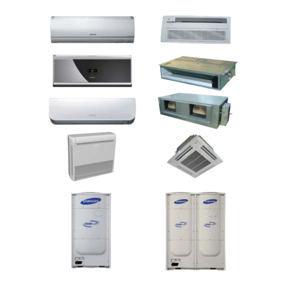
AIR CONDITIONER
Refer to the service manual in the GSPN(see the rear cover) for the more information.
SYSTEM AIR CONDITIONER
INDOOR UNIT
AVXCSH022/028/036EE
ND022/028/0361HXEA/XSE
AVXC2H056/071EE
AVXC4H045/056/071/090/112/128/140EE
AVXC4H045/056/071/090/112/128/140EG
ND045/056/071/090/112/128/1404HXEA/XSE
AVXCMH028/036/056/060EE
AVXDSH022/028/036/045/056/071/090/112/128/140EE
ND022/028/036/045/056/071/090/112/128/140LHXEA
ND022/028/036/045/056/071/090/112/128/140LHXEA/XSE
AVXDUH056/071/090/112/128/140EE
ND056/071/090/112/128/140SHXEA/XSE
ND140HHXEA
AVXDUH210/280EG
ND200/220/280HHXEA
ND200/220/280HHXEA/XSE
ND220/280HHXEASTK
AVXTFH056/071EE
ND056/071CHXEA/XSE
AVXTJH028/036/056EE
ND028/036/056JHXEA/XSE
AVXWBH028/036/056/071EE
ND028/036/056/071BHXEA/XSE
AVXWNH022/028/036/056/071EE
ND022/028/036/056/071NHXEA/XSE
ND022/028/036/045/056/071QHXEA
AVXWVH022/028/036/056/071EE
ND022/028/036/056/071VHXEA/XSE
ND0561/0711HXEH
ND022/028/036/045/056/071QHXEB
ND022/028/036/045/056/071QHXEBSTK
1. Precautions
2. Product Specifications
3. Disassembly and Reassembly
4. Troubleshooting
5. Exploded Views and Parts List
6. PCB Diagram and Parts List
7. Wiring Diagram
8. Schematic Diagram
9. Reference Sheet
OUTDOOR UNIT
RD080/100/120/140/160/180/200HHXGA
RD080/100/120/140/160/180/200HRXGA
RD080/100/120/140/160/180/200HHXGB
RD080/100/120/140/160/180/200HRXGB
RD080/100/120/140/160/180/200 HHXGASTK
RD080/100/120/140/160/180/200 HHXGASTK
RD080/100/120/140/160/180/200HHXGBXSE
CONTENTS
Advertisement
Table of Contents

Related Manuals for Samsung RD080HHXGB


Summarization of Contents
1. Precautions
1-1 Precautions for the Service
Guidelines for performing electrical and mechanical repairs on the product.
1-2 Precautions for Static Electricity and PL
Handling procedures to prevent damage from static discharge and potential hazards.
1-3 Precautions for the Safety
Essential safety measures to avoid electric shock, fire, and damage during operation.
1-4 Precautions for Handling Refrigerant
Safety and environmental guidelines for handling refrigerants, including frostbite and suffocation risks.
1-5 Precautions for Welding Pipes
Safety guidelines before and during welding, including removal of flammable objects and use of nitrogen gas.
1-6 Precautions for Refrigerant Supplement
Guidelines for accurately calculating and supplementing refrigerant to avoid product damage or container bursts.
1-7 Other Precautions
Additional precautions for installation, pipe connection, and refrigerant cycle integrity.
2. Product Specifications
2-1 The Feature of Product
Details on the product's world-class COP, low-temp heating ability, and core technologies.
2-2 Product Specifications
Detailed specifications for indoor units, including cooling/heating capacity, power, and dimensions.
2-3 Accessory and Option Specifications
List and specifications of optional accessories and kits available for the air conditioning system.
3. Disassembly and Reassembly
3-1 Indoor Unit
Step-by-step instructions for disassembling and reassembling indoor unit components like panels and fans.
3-2 Outdoor Unit
Procedure for disassembling and reassembling the outdoor unit, including cabinet, control box, and fan motor.
3-3 MCU
Detailed steps for disassembling and reassembling the MCU unit, including control box and front cabinet.
3-4 EEV KIT
Instructions for disassembling and reassembling the EEV kit components, including cabinet front and control parts.
4. Troubleshooting
4-1 Check-up Window Description
Description of the check-up window and functions on the outdoor unit PCB.
4-3 Diagnosis Checklist
Method for displaying and interpreting error codes based on number displays for outdoor units and MCUs.
4-4 Auto Inspect Mode
Procedure and operation range for the auto inspect mode to identify system abnormalities.
4-4-5 Error Code
List of error codes and their corresponding descriptions and causes for indoor units.
5. Exploded Views and Parts List
5-1 Indoor Unit
Exploded views and part lists for various indoor unit types, including cassette, duct, and wall-mounted models.
5-2 Outdoor Unit
Exploded views and part lists for various outdoor unit models, categorized by series and capacity.
6. PCB Diagram and Parts List
6-1 Indoor Unit
Detailed PCB diagrams and parts lists for various indoor unit types like Slim, Cassette, and Duct.
6-2 Outdoor Unit
PCB diagrams and parts lists for outdoor units, covering main PCB, EMI driver, and sub sensor boards.
6-3 Parts List
Comprehensive list of parts for PCB components, including connectors, resistors, capacitors, and integrated circuits.
7. Wiring Diagram
7-1 Indoor
Wiring diagrams for various indoor unit types, detailing connections for fan motor, sensors, and control parts.
7-2 Outdoor Unit
Wiring diagrams for outdoor units, illustrating connections for main PCB, HUB PBA, and power components.
8. Schematic Diagram
8-1 Indoor Unit
Schematic diagrams for indoor units, showing the layout of SMPS, EEV control, and communication parts.
8-2 Outdoor Unit
Schematic diagrams for outdoor units, detailing connections for main PCB, HUB PBA, and IPM components.
9. Reference Sheet
9-1 Index for Model Name
Index to understand the model code structure for indoor and outdoor units.
9-2 Refrigerant Circuit Diagram
Diagram illustrating the cycle operation mode of DVM PLUS 4 Europe Type, detailing component functions.
9-3 Pump-down Method
Procedure for safely pumping down refrigerant, with precautions for single and multiple outdoor unit installations.
9-4 How to Put Refrigerant in Refrigerant Container
Step-by-step guide on safely preparing and filling a rechargeable refrigerant container before pump-down.
Need help?
Do you have a question about the RD080HHXGB and is the answer not in the manual?
Questions and answers