
Related Manuals for GESTRA BAE 47


Summary of Contents for GESTRA BAE 47
- Page 1 Continuous blowdown valve BA 46 BA 47 BAE 46 BAE 47 Original Installation Instructions 818609-04...
-
Page 2: Table Of Contents
Contents Foreword ............................4 Availability ............................. 4 Formatting features in the document ...................... 4 Safety ..............................5 Use for the intended purpose ......................... 5 Basic safety notes ..........................5 Information on property damage or malfunctions ..................6 Qualification of personnel ........................7 Typographic features of warning notes .................... - Page 3 Dimensions and weights ........................39 Pressure & temperature ratings ......................43 Manufacturer's Declaration ......................45...
-
Page 4: Foreword
Make sure that this installation & operating manual efficiently for their intended purpose. is available to the operator. Continuous blowdown valve BA 46 (manual The installation & operating manual is part of the operation) equipment. Please hand over this installation &... -
Page 5: Safety
Usage for the intended purpose also includes remove the equipment or its components. reading and adhering to all instructions in the Only equipment types BA 46 and BA 47 may be installation and operating manual for the actuator (if used in potentially explosive atmospheres. -
Page 6: Information On Property Damage Or Malfunctions
Risk of severe injuries The connections of the electric actuator are live during operation. Take care not to touch The equipment is under pressure and can get connections during operation. Disconnect the hot during operation. Only perform work on the actuator from the power supply before equipment if the following conditions are performing any work on the equipment. -
Page 7: Qualification Of Personnel
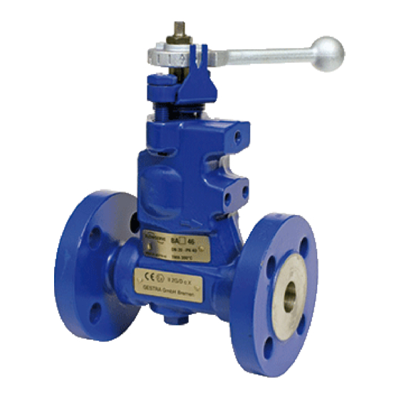
connecting the power supply of the actuator Scope of supply Typographic features of warning For equipment types BA 46 and BA 47, delivery notes includes the following: one continuous blowdown valve DANGER ... - Page 8 Equipment overview, BA Designation Designation Control lever Sealing plug Dial Sealing ring Body Stuffing box gland Rating plate Scale ATEX label (BA only)
- Page 9 With electric actuator, BAE Designation Designation Rating plate Control pin Actuator Thrust ring Bracket Spring Coupling The following actuators are available as standard: EF 10 EF 10-1 EF 0.7 EF 0.7-1 Other actuators are available on request. In these models, the opening signal can be sent by various controllers.
- Page 10 Inner parts Designation Designation Stuffing box gland Sampling valve Spring bushing Locking screw Wiper Sealing ring Guide bushing Nozzle needle Anti-wear bushing Packing ring Stepped bushings Disc springs Seat bushing Stuffing box screws...
- Page 11 The following items are indicated on the name plate: For equipment types BA 46 and BA 47, please note the following instructions for use in potentially Manufacturer explosive environments. Type designation ...
-
Page 12: Task And Function
Function Equipment types BA 46 and BA 47 are intended for manual operation. The required flowrate is calculated using a formula or can be seen in the The nozzle needle (25) is raised depending on the flow diagrams (see page 18). -
Page 13: Storing And Transporting The Equipment
Transporting the equipment Storing and transporting the equipment DANGER Attention! Risk of bruises if the equipment or component parts fall down. Equipment can be damaged if stored or transported improperly. Use suitable lifting gear when moving or lifting the equipment and/or ... -
Page 14: Mounting And Connecting The Equipment
Switch the installation off and protect it against Mounting and connecting the unauthorised or unintended re-activation. equipment To avoid waterhammer make sure that the pipe downstream of the equipment has a down Preparing installation gradient. Take the equipment out of the transport ... - Page 15 Make sure that the equipment is safely mounted Attention! and that all connections are made correctly. Risk of equipment damage or malfunction DANGER if incorrectly installed. Make sure that connections on the Danger of death from electric shock! steam generating unit have been ...
-
Page 16: Installing The Sampling Valve
Installing the sampling valve Positioning the control lever Remove the sealing plug (6). In BA models, you can change the position Remove the sealing ring (7) from the body. of the control lever by 180°. Insert the supplied sealing ring You will find information on the required A17 ×... -
Page 17: Starting Up The Equipment
Turn the dial (2) on the nozzle needle (25) to the Starting up the equipment desired position. Place the stuffing box gland (8) on the nozzle WARNING needle (25). Hand-tighten the stuffing box screws (28). Risk of burns from hot parts during operation. -
Page 18: Determining The Flowrate
Determining the flowrate A = (Q × S) / (K – S) whereby: The possible flowrate as a function of the A = quantity of boiler water to be drained [kg/h] differential pressure is presented in the following diagrams. Q = boiler capacity [kg/h] To improve clarity, the flow diagrams for DN 15 to S = feedwater conductivity [㎲/cm] DN 32 and those for DN 40 and DN 50 are each... - Page 19 Flow diagram for DN 15 to DN 32, capacity range up to 310 kg/h...
- Page 20 Flow diagram for DN 15 to DN 32, capacity range up to 1,020 kg/h...
- Page 21 Flow diagram for DN 15 to DN 32, capacity range up to 2,120 kg/h...
- Page 22 Flow diagram for DN 40 and DN 50, capacity range up to 1,340 kg/h...
- Page 23 Flow diagram for DN 40 and DN 50, capacity range up to 4,500 kg/h...
- Page 24 Flow diagram for DN 40 and DN 50, capacity range up to 6,300 kg/h...
-
Page 25: Operating The Equipment
Normal operation If the actuator fails in BAE 46 or BAE 47 models, you can adjust the flowrate manually. Proceed as For BA 46 or BA 47 models without actuator, follows: proceed as follows: Disconnect the actuator from the electricity ... -
Page 26: After Operation
Removing external dirt deposits After operation Use fresh water and a cloth to remove dirt and contaminants from the equipment body. WARNING Risk of severe injury or death due to burns Required tools for servicing during work on pipes. ... -
Page 27: Maintaining The Equipment
Maintaining the equipment Maintenance schedule Interval Component Activity Daily Nozzle needle Move nozzle needle by at least one full stroke. 3 months Stuffing box seal Visually inspect to ensure tightness. Replace a leaky stuffing box. Visually inspect for the following points: ... -
Page 28: Servicing The Equipment And Installing Spare Parts
Servicing the equipment and installing spare parts You may exchange the following component parts in case of wear or damage:... - Page 29 Designation Stock code BA 46 BAE 46 BA 47 BAE 47 335702 335702 7, 17, Packing and sealing set DN 15–32, 24, 26 comprising: Packing ring 15 × 23 × 8 with 4 wipers Sealing ring C 6 × 10 × 1.5 ...
- Page 30 Replacing the actuator Replacing the stuffing box and inner parts If the stuffing box bush cannot be sealed using the DANGER set torque, or the control lever can no longer be moved, replace the stuffing box with a new one. Danger of death from electric shock! ...
- Page 31 Remove the disc springs (27). Using a brass punch (34), knock the following inner parts out of the body as shown. Remove the spring bushing (16). Unscrew the nozzle needle (25) from the body. Stuffing box with packing ring (26) and four wipers (17) ...
- Page 32 Clean all removed parts and the body. Position the guide bushing (18) so that the retaining groove points towards the locking Inspect all parts to ensure they are in perfect screw. condition. Insert the guide bushing (18). ...
- Page 33 Turn the dial (2) on the nozzle needle (25) to the Insert the sealing ring (7). desired position. Screw in the sealing plug (6) or sampling valve Place the stuffing box gland (8) on the nozzle to a torque of 130 Nm.
-
Page 34: Retrofitting An Actuator
Retrofitting an actuator You can convert the manually operated BA to a BAE with electric actuator. You will need a retrofit kit to do this. A retrofit kit without actuator is available if you already have one. Designation Contents Stock code Actuator EF 0.7 336810 ... - Page 35 also need to adjust the feedback potentiometer, if Install the actuator as follows: present. Insert the spring (15) and thrust ring (14) in the Make sure the "CLOSED" switch cam is actuator (10). adjusted in the actuator in such a way that the ...
-
Page 36: Troubleshooting
Troubleshooting Problem Cause Remedy Fluid escapes (equipment is The equipment or the body is Replace the equipment with a new one. leaking). damaged. Fluid escapes (equipment is A gasket is damaged. Replace the gasket with a new one. leaking). Clean gasket seating surfaces. Fluid escapes (equipment is The connections are not tight. -
Page 37: Putting The Equipment Out Of Operation
Re-using equipment after storage Putting the equipment out of operation Observe the following instructions if you want to remove the equipment and use it again somewhere else: Removing the equipment Make sure that the equipment is free of any fluid residues. -
Page 38: Disposing Of The Equipment
Disposing of the equipment The equipment is made from the following materials: Component DIN/EN ASTM Body 1.0460 A 105 Stuffing box gland 1.0570 – Stuffing box screws A2-70 – Stuffing box PTFE yarn PTFE yarn Sealing plug 1.7225 A 193 B7 Sealing ring 1.4301 –... -
Page 39: Technical Data
Technical data Dimensions and weights... - Page 40 BA 46 and BAE 46, flange PN 40 and ASME CLASS 150 and CLASS 300 [mm] [in] ½ ¾ 1¼ 1½ D (BAE only) [mm] [mm] H2 (BA) [mm] H3 (BAE) [mm] [mm] (PN 40, CLASS 150) (CLASS 300) [mm]...
- Page 41 [mm] [mm] S2 (BA) [mm] S3 (BAE) Weight (BA) [kg] 10.7 12.5 Weight (BAE) 11.2 14.8 16.6 BA 46/47 and BAE 46/47, butt-weld end [mm] [in] ½ ¾ 1¼ 1½ D (BAE only) [mm] [mm] H2 (BA) [mm] H3 (BAE)
- Page 42 BA 46/47 and BAE 46/47, socket-weld end [mm] [in] ½ ¾ 1¼ 1½ D (BAE only) [mm] [mm] H2 (BA) [mm] H3 (BAE) [mm] [mm] [mm] S2 (BA) [mm] S3 (BAE) Weight (BA) [kg] Weight (BAE) 12.4 13.6 BA 47 and BAE 47 in DN 25, 40, 50 only...
- Page 43 Pressure & temperature ratings Pressure and temperature ratings of BA 46 and BAE 46 Type of connection PN 40 flange and EN butt-weld ends Pressure p [bar] 40.0 37.1 33.3 27.6 Temperature T [°C] Operating limits for strength of body/cover to EN 1092-1 Operating data: Maximum pressure 31 [bar] at boiling temperature 237.5 [°C]...
- Page 44 Pressure and temperature ratings of BA 47 and BAE 47 Type of connection PN 63 flange, socket-weld ends and butt-weld ends Pressure p [bar] 63.0 58.5 52.5 43.5 Temperature T [°C] Operating limits for strength of body/cover to EN 1092-1 Operating data: Maximum pressure 46.7 [bar] at boiling temperature 261 [°C] Type of connection CLASS 600 flange, socket-weld ends and butt-weld ends...
- Page 45 Assessment according to European rules refer to our Declaration of Conformity or our Declaration by Manufacturer. To download the current Declaration of Conformity or Declaration by Manufacturer go to www.gestra.com/documents or contact: GESTRA AG Münchener Straße 77 28215 Bremen Germany...
- Page 48 Agencies all over the world: www.gestra.de GESTRA AG Münchener Strasse 77 28215 Bremen Germany Phone +49 421 3503-0 +49 421 3503-393 e-mail info@de.gestra.com www.gestra.com 818609-04/03-2019_kx_mm (808708-06) © GESTRA AG Bremen Printed in Germany...
Need help?
Do you have a question about the BAE 47 and is the answer not in the manual?
Questions and answers