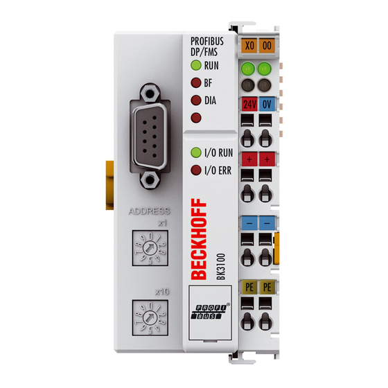
Table of Contents
Advertisement
Advertisement
Chapters
Table of Contents

Summarization of Contents
Foreword
Product Overview Bus Couplers for PROFIBUS DP
Introduces the range of Bus Couplers for PROFIBUS DP.
Notes on the Documentation
Details intended audience, disclaimer, trademarks, and patent info.
Safety Instructions
Provides essential safety regulations, warnings, and hazard symbols.
Documentation Issue Status
Lists changes and updates across different document versions.
Product Overview
BK30x0, BK3100, BK3110, BK3120, LC3100 - Technical Data
Presents technical specifications for various bus coupler models.
BK3150 - Technical Data
Details the technical specifications for the BK3150 bus coupler.
BK35x0 - Technical Data (Optical Fibers)
Provides technical specifications for BK35x0 bus couplers with optical fibers.
The Beckhoff Bus Terminal System
Describes the universal interface between fieldbus and sensor/actuator levels.
PROFIBUS Introduction
Introduces the PROFIBUS DP communication protocol.
PROFIBUS DP
Explains the master-slave communication and DP startup process.
Mounting and Wiring
Instructions for ESD Protection
Details precautions for preventing electrostatic discharge damage.
Dimensions
Explains the physical size and modularity of the Bus Terminal system.
Mounting
Describes how to mount the Bus Couplers and terminals on a rail.
Connection
Covers connection options and system types.
Connection System
Explains different connection systems like standard and pluggable wiring.
Wiring
Guides on how to wire the terminals using spring force technology.
Potential Groups, Insulation Testing and PE
Details potential groups, insulation testing, and PE connections.
Power Supply
Explains the 24 VDC operating voltage and connection points.
BKxx50 and BKxx51 Power Supply
Details 24 VDC supply for BKxx50/BKxx51 and UL requirements.
PROFIBUS Cabling
Covers PROFIBUS cabling standards, connectors, and properties.
PROFIBUS Connection
Covers M12 and D-Sub connectors and pin assignments for PROFIBUS.
Fieldbus Box Module Connection
Explains direct or T-piece connection of Fieldbus Box modules.
RS485 Fundamental Properties
Details RS485 transmission properties according to PROFIBUS standard.
Recommended Cables
Recommends using preassembled cables for straightforward installation.
ATEX
ATEX - Special Conditions (Standard Temperature Range)
Details special conditions for use in potentially explosive areas.
ATEX - Special Conditions (Extended Temperature Range)
Lists special conditions for ET components in explosive areas.
ATEX Documentation
Notes about ATEX terminal systems in potentially explosive areas.
Parameterization and Commissioning
Start-up Behaviour of the Bus Coupler
Describes the self-test and operational states during startup.
The Bus Coupler's UserPrmData
Explains configurable settings via UserPrmData for system behavior.
Technical Data - Overview
Provides a comparative overview of technical data for various models.
Configuration
Outlines the process for configuring bus coupler functions and modules.
Configuration - CfgData
Explains CfgData generation from DP configuration tool modules.
Configuration of the Coupler Modules
Details adding DP modules for coupler functions like PLC interface.
Configuration of Complex Modules
Lists complex terminals and their associated CfgData hex codes.
Configuration of Digital Modules
Guides on configuring digital terminals based on input/output bit counts.
GSD Files
Explains the role of GSD files for PROFIBUS coupler integration.
KS2000 - Introduction
Introduces the KS2000 software for configuration and commissioning.
Configuration via TwinCAT
Describes configuring PROFIBUS DP via TwinCAT automation software.
Configuration with Siemens S7 Controller
Details configuration steps for Siemens S7 controllers.
Configuration: Siemens S7 Controller BK3120
Explains parameter data and configuration for BK3120 in S7.
PROFIBUS DP Communication
DataExchange - Cyclic Data Exchange
Explains how data is exchanged cyclically between master and slave.
Process Data, Process Image
Describes how process data is mapped into the controller's process image.
K-bus Cycle
Details K-bus cycle modes and synchronization with DP cycle.
DPV1 - Acyclic Data Transfer
Explains acyclic data transfer using DPV1 services.
DPV1 Interface
Describes the MSAC_C1 and MSAC_C2 connections for DPV1.
Assignment of the DPV1 Slot Number
Explains how slot numbers are assigned for DPV1 data access.
DPV1 at the Coupler
Details DPV1 module assignment, firmware, and terminal composition.
Module Assignment
Details DPV1 module assignment for multi-configuration mode.
Firmware Information
Explains how to read firmware information via DPV1.
Terminal Composition
Describes how to read terminal composition and length via DPV1.
K-bus Status
Details how to read K-bus status via DPV1.
Cycle Time Measuring
Explains how to start, stop, and read cycle time measurements via DPV1.
Diagnostics and Error Handling
LEDs
Explains the meaning and states of the Bus Coupler's LEDs.
DP Diagnostics
Covers DP standard and device-specific diagnostic data.
DP Diagnostic Data (DiagData)
Explains the structure and meaning of DP diagnostic data.
DP Start-up Errors
Lists and explains error codes and arguments during DP startup.
Reaction to PROFIBUS Error
Describes how the coupler reacts to PROFIBUS errors.
K-bus Diagnosis
Covers K-bus errors, interruptions, and diagnosis.
K-bus Interruption
Details reactions and resets for K-bus interruptions.
Terminal Diagnostics
Explains how to activate and interpret terminal diagnostics.
Extended Functions
2-byte PLC Interface
Describes the 2-byte PLC interface for configuration and data exchange.
Word Alignment
Explains word alignment for clear I/O data in controllers.
Deactivating the CfgData Check
Allows deactivation of CfgData checking for flexible configuration.
Multi-Configuration Mode
Enables flexible configurations with varying hardware setups.
Changing the Size of the Process Data
Details how to adjust DP buffer sizes for input, output, and config data.
Bus Coupler Versions in Multi-Configuration Mode
Illustrates how multi-configuration mode applies to production machines.
Appendix
General Operating Conditions
Lists environmental conditions and protection classes for operation.
Approvals
Provides information on UL and CE approvals.
Bibliography
Lists books and standards related to PROFIBUS and fieldbus technology.
List of Abbreviations
Defines common abbreviations used in the document.
Support and Service
Provides contact details for Beckhoff support and service centers.


Need help?
Do you have a question about the LC3100 and is the answer not in the manual?
Questions and answers