Sign In
Upload
Download
Table of Contents
Contents
Add to my manuals
Delete from my manuals
Share
URL of this page:
HTML Link:
Bookmark this page
Add
Manual will be automatically added to "My Manuals"
Print this page
×
Bookmark added
×
Added to my manuals
Manuals
Brands
Reer Manuals
Control Unit
MBEC
Installation and use manual
Reer MBEC Installation And Use Manual
Fieldbus module
Hide thumbs
Also See for MBEC
:
Manual
(22 pages)
1
2
3
4
5
6
7
8
9
10
11
12
13
14
15
16
17
18
19
20
21
22
23
24
Table Of Contents
25
26
27
28
29
30
31
32
33
34
35
36
37
38
39
40
41
42
43
44
45
46
47
48
49
50
51
52
53
54
55
56
page
of
56
Go
/
56
Contents
Table of Contents
Bookmarks
Table of Contents
Table of Contents
Version History
General Notes
Ethercat (MBEC)
PDO Overview
Process Data Mapping (PDO)
Vendor Specific Objects
Object Index 2001H - System Status
Object Index 2003H - Errors Data CPU 0
Object Index 2004H - Errors Data CPU 1
Object Index 2005H - Input Diagnostics
Object Index 2006H - OSSD Diagnostics
Object Index 2007H - Project CRC
Object Index 2101H - Fieldbus Inputs
Object Index 2181H - Fieldbus Inputs Feedback
Object Index 2201H - Input Status
Object Index 2202H - OSSD Status
Object Index 2203H - Probe Status
Object Index 2204H - Analog Data
Canopen (MBC)
PDO Overview
Process Data Mapping (PDO)
Vendor Specific Objects
Object Index 2001H - System Status
Object Index 2003H - Errors Data CPU 0
Object Index 2004H - Errors Data CPU 1
Object Index 2005H - Input Diagnostics
Object Index 2006H - OSSD Diagnostics
Object Index 2007H - Project CRC
Object Index 2101H - Fieldbus Inputs
Object Index 2181H - Fieldbus Input Feedback
Object Index 2201H - Input Status
Object Index 2203H - Probe Status
Object Index 2204H - Analog Data
Ethernet/Ip (MBEI)
Process Data Mapping (Class 1 Connection)
Assembly Instance 96H (Connection Point T->O Consuming Instance)
Assembly Instance 64H (Connection Point O->T Producing Instance)
Assembly Instance 05H (Configuration Data)
Explicit Messaging
Devicenet (MBD)
Process Data Mapping
Assembly Instance 96H (Consuming Instance)
Assembly Instance 64H (Producing Instance)
Explicit Messaging
Modbus TCP/IP (MBEM)
Modbus Serial (MBMR)
Register Mapping
Holding Registers (4X)
Profinet (Mbep)
Process Data Mapping
Record Data Read/Write Services
Profibus Dp (Mbp)
Process Data Mapping
Record Data Read/Write Services
Acyclic Data Format
Errors Data Cpux Format
Input Diagnostics Format
OSSD Diagnostics Format
Project CRC Format
Advertisement
Quick Links
1
Table of Contents
2
General Notes
3
Pdo Overview
4
Process Data Mapping (Pdo)
5
Modbus Tcp/Ip (Mbem)
6
Profinet (Mbep)
7
Process Data Mapping
Download this manual
Mosaic fieldbus modules
8540467 • 04/10/2018 • Rev.0
1
Table of
Contents
Previous
Page
Next
Page
1
2
3
4
5
Advertisement
Table of Contents
Need help?
Do you have a question about the MBEC and is the answer not in the manual?
Ask a question
Questions and answers
Related Manuals for Reer MBEC
Controller Reer Mosaic Series Manual
Fieldbus modules (22 pages)
Control Unit Reer Mosaic MO4LHCS8 Quick Installation Manual
High current output expansion unit (2 pages)
Control Unit Reer Mosaic Series Installation And Use Manual
Fieldbus module (56 pages)
Control Unit Reer MBEI Installation And Use Manual
Fieldbus module (56 pages)
Control Unit Reer MBEP Installation And Use Manual
Fieldbus module (56 pages)
Control Unit Reer MBEM Installation And Use Manual
Fieldbus module (56 pages)
Control Unit Reer MOSAIC Micron Installation And Use Manual
Fieldbus modules (55 pages)
Control Unit Reer Micron MI-BUS Quick Start Manual
Fieldbus modules (2 pages)
Control Unit Reer JANUS MJBOX Manual
Interconnection modules (8 pages)
Control Unit Reer ARGOLUX AU S3M2 Installation, Use And Maintenance Manual
Control unit with integrated muting function (32 pages)
Control Unit Reer ARGOLUX AU S-TWIN Installation And Use Manual
(14 pages)
Control Unit Reer Aus X Series Use And Maintenance
(39 pages)
Control Unit Reer SR X Installation, Use And Maintenance Manual
Safety relay module (22 pages)
Control Unit Reer SR ZERO A Installation, Use And Maintenance Manual
Safety relay module (15 pages)
Summarization of Contents
Mosaic Fieldbus Modules Installation and Use
Introduction to Mosaic Fieldbus Modules
Mosaic Fieldbus Module Electrical Connections
Module Signals and Pinout Overview
Module MBC Signals and Pinout
Details on signals, pinout, and LED indicators for the MBC module.
Module MBD Signals and Pinout
Details on signals, pinout, and LED indicators for the MBD module.
Module MBP Signals and Pinout
Details on signals, pinout, and LED indicators for the MBP module.
Module MBEC Signals and Pinout
Details on signals, pinout, and LED indicators for the MBEC module.
Module MBEI Signals and Pinout
Details on signals, pinout, and LED indicators for the MBEI module.
Module MBEI2B Signals and Pinout
Details on signals, pinout, and LED indicators for the MBEI2B module.
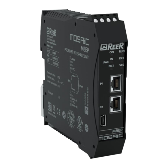
Module MBEP Signals and Pinout
Details on signals, pinout, and LED indicators for the MBEP module.
Module MBEP2 Signals and Pinout
Details on signals, pinout, and LED indicators for the MBEP2 module.
Module MBEM Signals and Pinout
Details on signals, pinout, and LED indicators for the MBEM module.
Module MBCCL Signals and Pinout
Details on signals, pinout, and LED indicators for the MBCCL module.
Module MBMR Signals and Pinout
Details on signals, pinout, and LED indicators for the MBMR module.
Module MBU Signals and Pinout
Details on signals, pinout, and LED indicators for the MBU module.
Mosaic Fieldbus Module Description and Process Image
Mosaic Fieldbus Module Diagnostics
The I/O Index Field for Diagnostics
Details on the I/O index used to identify I/O with non-OK diagnostic codes.
Diagnostic Code Field Meanings
Explanation of diagnostic codes and their meanings for I/O.
Input Diagnostics Codes
Table listing diagnostic codes and their meanings for input signals.
Output Diagnostics Codes
Table listing diagnostic codes and their meanings for output signals.
Examples of Mosaic Fieldbus Diagnostics
Diagnostic Example 1: Connection Error
Demonstrates diagnostics for input 1 with a connection error scenario.
Diagnostic Example 2: Logical Block Indexing
Illustrates I/O index correspondence to logical blocks, not physical terminals.
Diagnostic Example 3: Error Codes
Shows diagnostics for input 1 and OUT_TEST with specific error codes.
Diagnostic Example 4: OSSD Restart Wait
Illustrates diagnostics for OSSD with waiting for restart status.
Mosaic Bus Configurator User Interface
Bus Configurator Graphical Interface
Detailed description of the Bus Configurator graphical interface and its functions.
Backward Compatibility for M1 FW < 5.0.0
Graphical Interface for Backward Compatibility
Using the Bus Configurator with older M1 master firmware versions.
MSD Configuration Examples with Bus Configurator
MV Modules Input Status Overview
Table of Contents
Print
Rename the bookmark
Delete bookmark?
Delete from my manuals?
Login
Sign In
OR
Sign in with Facebook
Sign in with Google
Upload manual
Upload from disk
Upload from URL
Need help?
Do you have a question about the MBEC and is the answer not in the manual?
Questions and answers