Table of Contents
Advertisement
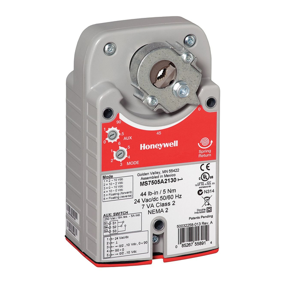
N314
MS3103, MS3105, MS4103, MS4105, MS7403, MS7405,
MS7503, MS7505, MS8103, MS8105 Spring Return Direct
Coupled Actuators (DCA) are used within heating, ventilating,
and air-conditioning (HVAC) systems. They can drive a variety
of quarter-turn, final control elements requiring spring return
fail-safe operation.
Applications include:
• Volume control dampers, mounted directly to the drive
shaft or remotely (with the use of accessory hardware).
• Quarter-turn rotary valves, such as ball or butterfly valves
mounted directly to the drive shaft.
• Linear stroke globe or cage valves mounted with linkages
to provide linear actuation.
• Available with cable on select models
Model Number
Model Number
(including 3 ft. whip)
MS3103J1030
MS7403A2030
MS7503A2030
MS7503A2130
MS8103A1030
MS8103A1130
MS4103A1030
MS4103A1130
MS3105J3030
MS3105J3130
MS7405A2030
MS7505A2030 MS7505W2030
MS7505A2130 MS7505W2130
MS8105A1030 MS8105W1030
MS8105A1130 MS8105W1130
MS4105A1030
MS4105A1130
1
Number represents range
2
2-10 Vdc
3
0/2-10 Vdc
3 Nm, 5 Nm Series Spring Return
Direct Coupled Actuators
MS3103, MS3105, MS4103, MS4105, MS7403, MS7405, MS7503,
MS7505, MS8103, MS8105
Table 1. Models.
Power Supply
VA
Torque
Voltage
Driving
27 lb-in
24 Vac/dc
6/3
(3 Nm)
@50/60 Hz +/-
20%
24Vdc+/-10%
100-250 Vac
6/9
@50/60Hz
44 lb-in
24 Vac/dc
6/3
(5 Nm)
@50/60 Hz +/-
20%
24Vdc+/-10%
100-250 Vac
6/9
@50/60Hz
INSTALLATION INSTRUCTIONS
SPECIFICATIONS
Models:
See Table 1.
Device Weight:
3.5 lbs (1.60 kg)
Ambient Operating Temperature:
-40° to 150°F (-40° to 65°C)
-22° to 150°F (-30° to 65°C) (Two position only)
Shipping and Storage Temperature:
-40° to +150°F (-40° to +65°C)
Drive
1
(sec)
Control Input/Output Description
90
Sylk-enabled
2
Floating, Modulating
3
Floating, Modulating
45
Two-Position (SPST)
45
Two-Position (SPST)
90
Sylk-enabled (5 addresses & Analog Output)
2
Floating, Modulating
3
Floating, Modulating
45
Two-Position (SPST)
45
Two-Position (SPST)
,Three-Position, Feedback
, and Feedback
, Three-Position, Feedback
, and Feedback
62-0274-07
SPDT
Aux
Switch
0
0
0
1
0
1
0
1
0
1
0
0
1
0
1
0
1
Advertisement
Table of Contents

Related Manuals for Honeywell MS4103A1130


Summarization of Contents
Installation
Location
Details on actuator mounting location and shaft coupling use.
Determine Appropriate Mounting Orientation
Guides setting actuator rotation direction for opening the damper.
Non-Standard Stroke
Mechanical Stroke Limit Reduction
Procedure for adjusting actuator stroke to less than 95 degrees.
Control Signal and Position Selection
Using Auxiliary Knob and mode dials for control signal and position settings.
Wiring
Access Cover Removal
Steps for safely removing the actuator's access cover for wiring.
Typical Wiring Without Cables
Wiring diagrams for actuators without cables (whips).
Operation
Actuator Override
Methods to override normal control for freeze protection or similar applications.
Checkout
Typical Wiring With Cable
Wiring diagrams for actuators with cables (whips).
End Switches
Information on models with adjustable end switches.
Modulating/Floating Operation
Procedure to verify modulating and floating control operations.
Spring Return Operation
Procedure to verify spring return functionality and 0% position.
Feedback Operation
Procedure to check feedback signal readings against input signals.
Direct Checkout
Steps to verify direct control operation of the actuator.
Two-Position Checkout
Procedure to verify two-position control operation.
Sylk-enabled (S-BUS) Checkout
Steps to verify Sylk-enabled (S-BUS) controller integration.
Need help?
Do you have a question about the MS4103A1130 and is the answer not in the manual?
Questions and answers