Table of Contents
Advertisement
Advertisement
Table of Contents

Related Manuals for East 30KVA


Summary of Contents for East 30KVA
-
Page 2: Table Of Contents
Table of Contents 1 Safety Information ....................1 1.1 Symbol instructions ....................... 1 2 Product Overview ....................3 2.1 Product description ........................ 3 2.2 Product features ........................3 2.3 Specifications ......................... 4 2.4 Front view of the UPS......................6 3 Installation ......................9 3.1 Transportation or movement .................... - Page 3 5 Operation Modes ....................28 5.1 Mains inverter mode ......................28 5.2 Battery mode ......................... 28 5.3 Bypass mode......................... 29 5.4 Maintenance mode ....................... 29 5.5 Fault mode ..........................30 6 Routine Maintenance ..................33 6.1 Application and maintenance of storage batteries ............33 6.2 UPS maintenance .........................
-
Page 4: Safety Information
1 Safety Information CAUTION Non-qualified electricians are forbidden to open the case due to hazard of electrical shock. Consulting the dealer is required before using for below equipment. Its application, configuration, management and maintenance must be specially considered and designed. ... - Page 5 Do not open or destroy the batteries, the strong toxicity of the overflowing electrolyte will do harm to human bodies. Please avoid the short circuit of battery anodes and cathodes. Otherwise, it will cause electric shocks or ignition. Please do not open the UPS housing by yourself.
-
Page 6: Product Overview
2 Product Overview 2.1 Product description This series on-line UPS is a high-performance and full-digital uninterruptible power supply using the DSP control technology. The system uses online double-conversion topology design. The DC/AC converter adopts SPWM technology, IGBT power module, and output isolation transformer. Therefore, This series UPS is a kind of pure sine wave power supply with stable frequency stable voltage (SFSV) output and without being affected by grid interference. -
Page 7: Specifications
RS232 and USB communication for standard configuration; RS485, SNMP, and dry contact for options. Battery cold start Manual maintenance 2.3 Specifications Model 6KVA 10KVA 10KVA 15KVA 20KVA 30KVA Online power supply, static bypass switch (uninterruptible Operating Mode & Principle... - Page 8 Voltage Transient <20ms Recovery Time Output Current Peak 3: 1 Ratio Waveform Distortion <3% (linear load); <6% (non-linear load) Mains power mode to battery mode: 0ms; Switching Time Bypass mode to inverter mode: 0ms Load ≤105%: long time working; 105%< load ≤125%: transfer to bypass output in 10min; Overload Capacity 125%<...
-
Page 9: Front View Of The Ups
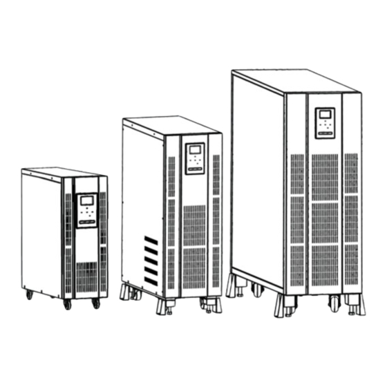
2.4 Front view of the UPS UPS net dimensions (mm) 6KVA 10KVA 30KVA Front panel and rear panel features 6KVA front and rear panel... - Page 10 ① SNMP port ⑤Mains input breaker ⑨Fan ②USB port ⑥Bypass input breaker ⑩Terminal block ③ EPO port ⑦Output breaker ⑪Display panel ④RS232 port ⑧Maintenance bypass breaker 10KVA (1/1) front and rear panel ①EPO port ⑤Mains input breaker ⑨ SNMP port ②USB port ⑥Bypass input breaker ⑩Terminal block...
- Page 11 30KVA (3/3) front and rear Panel ①EPO port ⑤ SNMP port ⑨Maintenance bypass breaker ②USB port ⑥Mains input breaker ⑩Terminal block ③ RS232 port ⑦Bypass input breaker ⑪Display panel ④Parallel port ⑧Output breaker...
-
Page 12: Installation
3 Installation 3.1 Transportation or movement Considering the outermost shell of this product being shield, the protective cover cannot be used as the force bearing parts for transportation. It is necessary to pay attention to the following points, so as to ensure the safety: ... -
Page 13: Installation Environment And Location
Screw Input Input Input Wire Hole 6KVA (1: 1) 10KVA (1: 1) 10KVA (3: 1) 15KVA (3: 1) 20KVA (3: 1) 30KVA (3: 1) Note: During the wiring, make sure to respectively connect the input and output cables with the input and output terminals firmly. -
Page 14: Single Wiring
Wiring schematic diagram for 1-phase in/1-phase out UPS: Ground Input Bypass Battery Output wire INPUT BATTERY OUTPUT BYPASS Wiring schematic diagram for 3-phase in/1-phase out UPS: Ground Input Bypass Battery Output wire INPUT BYPASS BATTE OUTPUT 3.3.3 Single wiring After fully positioning the equipment, connect the power cord according to the following steps: Make sure that all the input power distribution switches and internal power switches of UPS ... -
Page 15: Parallel Ups Units
The bypass refers to the short-circuit wire that shall be used for disconnecting the mains power and bypass on the terminal block when the mains power uses duplex mains input, which is the short-circuit wire of the bypass input cable L and the mains input cable L (1-phase in/1-phase out UPS), or the mains input cable C (3-phase in/1-phase out UPS). - Page 16 DB15公座 DB15母座 DB15公座 DB15母座 DB15 Male Socket DB15 Male Socket DB15 Female Socket DB15 Female Socket UPS1 UPS2 Connect power cables for parallel UPS units After fully positioning the equipment, use the input and output cable of the parallel system to respectively connect the input ends of each UPS together, and the output ends of each UPS together.
-
Page 17: Operation Instructions
4 Operation Instructions 4.1 Panel instructions 4.1.1 Display panel Keys Descriptions MUTE 4.1.2 LED indicators REC: Rectification Indicator INV: Inverter Indicator OUTPUT: Output Indicator BYP: Bypass Indicator BAT: Battery Indicator... -
Page 18: Lcd Screen
The indicator status description is shown in the table below. Indicator Function Description Rectification Indicator Light on: The rectifier is running. ① (green) Light off: The rectifier is out of operation. Light on: The inverter is turned on. Inverter Indicator ②... -
Page 19: Keys
Press the setting button in standby mode, so as to enter the function setting status for manual bypass setting, output voltage setting, output frequency setting, physical address setting, UPS self-inspection function (p) setting (fault elimination function), etc. Power level and operating mode display area: ... -
Page 20: Function Settings
Load: Display the values of “active power” and “apparent power” at this moment. As shown in the figure below, the load capacity is 8.0kW/10.0kVA. Input: Display input voltage and input frequency. As shown in the figure below, the input voltage is 220V, and the input frequency is 50.0Hz. - Page 21 The settable functional items of 6-30KVA UPS are shown in the table below: Serial Display Function Instructions Remark Output Voltage The output voltage can be set at220V/230V/240V 220V by default Setting Output Frequency The output frequency can be set at 50.0Hz/60.0Hz 50.0Hz by default Setting Physical Address...
- Page 22 After selecting the numerical value, short press the function setting key , so as to confirm the OPU setting. At this moment, the numerical value on the right side of the word “OPU” is always lit up without blinking. ...
- Page 23 Enter the physical address ID setting interface by short pressing the function setting key At this moment, the word “ID” is always lit up, and the numerical value showing up on the right side of the word “ID” blinks at the same time. Select the numerical value corresponding to the ID function by short pressing the left key or the right key .
-
Page 24: Daily Startup And Shutdown
4.2.2.5 UPS self-inspection function (p) settings (Fault elimination function) UPS Self-inspection functional interface Enter the setting interface by short pressing the function setting key . Select the function setting by short pressing the left key or the right key . -
Page 25: Manual Bypass
Users cannot operate the components at the back of the protective cover plates, which can only be opened by using tools. Only qualified maintenance personnel can be allowed to open such protective cover plates. Check the rear panel, so as to confirm that all the switches have been disconnected. ... -
Page 26: Battery Cold Start
switch. Enter the setting interface by pressing for 0.5s. Select the nbp interface by pressing for 0.5s. Press key for confirmation. Select “nbp ON” by pressing for 0.5s again. Press key for confirmation. UPS enters the forced bypass mode afterwards. ... -
Page 27: Shutdown Procedures (Completely Shutting Down The Ups And Loads)
4.3.5 Shutdown procedures (Completely shutting down the UPS and loads) Follow the steps below when completely shutting down the UPS and disconnecting the loads. Disconnect all the power switches and breakers. The loads are no longer powered by UPS. Disconnect all the UPS loads. ... -
Page 28: Reset Operation After The Fault Alarm
4.3.7.2 Shutdown parallel UPS Turn off all the loads. Press the shutdown key combination to turn off the UPS1, UPS2…UPSN. Single Exit: Turn off the UPS to be exited, and disconnect its mains, bypass and battery switches under the condition of system inverter output. Please check the capacity before single exit, so as to make sure that the parallel system will not overload after single exit. -
Page 29: Communication Interface
4.4 Communication interface 4.4.1 Computer interface UPS and monitoring equipment (computer) can be connected with each other through standard RS232 port (standard configuration) and standard USB interface (standard configuration), so as to realize single UPS communication. Connect RS232 (USB) communication cable onto the serial port (USB interface) of the computer;... - Page 30 Remove the cover plate on the intelligent slot first; Insert the required intelligent card in the slot; Use the screws removed before to fasten the intelligent card. > SNMP card (Optional) SNMP cards can be compatible with the software, hardware, and network operating systems that are popular on the Internet today.
-
Page 31: Operation Modes
5 Operation Modes This series UPS is online double-conversion UPS system, which can be operated in the following modes: Mains inverter mode Battery mode Bypass mode Maintenance mode (manual bypass) Parallel redundancy mode 5.1 Mains inverter mode Mains power provides AC power supply for the UPS rectifier. -
Page 32: Bypass Mode
Battery mode 5.3 Bypass mode If UPS remains shutdown status after being electrified, and suffers from inverter fault in the inverter power supply mode, or is turned off, UPS will switch to bypass mode. Bypass mode (the inverter has been shut down) Caution: When UPS is in bypass mode, if voltage and frequency fluctuation occur, or UPS suffers from power failure, the loads will not be under the protection of UPS. -
Page 33: Fault Mode
Maintenance mode 5.5 Fault mode The LED indications during the operation in fault mode are shown in the figure below: All the LED indicators go out, and the fault icons and codes show up in the LCD display area at the same time. When UPS breaks down, the buzzer gives out long beep. - Page 34 Alarm messages Alarm Definition Code Description UPS Action Sound When the system is set to be Parallel lock phase 2 beeps/s paralleled, lock phase abnormality Give an alarm abnormality is detected on this unit. Bypass sampling frequency is Frequency beyond Give an alarm, UPS inverter 2 beeps/s beyond...
- Page 35 Alarm messages Alarm Definition Code Description UPS Action Sound Low-voltage The inverter voltage is lower than the Shut down and switch to Long Beep inverter fault configured fault alarm point bypass High-voltage The inverter voltage is higher than the Shut down and switch to Long Beep inverter fault configured fault alarm point...
-
Page 36: Routine Maintenance
6 Routine Maintenance 6.1 Application and maintenance of storage batteries Battery safety description: The battery life will be shortened along with the rise of ambient temperature. Battery shall be periodically replaced to guarantee the normal operation of UPS, and enough backup time shall be guaranteed. -
Page 37: Ups Maintenance
Clean up the dust and dirt on the batteries. Check whether all the internal connecting wires of batteries are loose or corroded. Conduct replacement and maintenance if necessary. Make sure that the batteries and the battery terminals are fastened. 6.2 UPS maintenance This series of UPS only needs to be maintained for a few times.
Need help?
Do you have a question about the 30KVA and is the answer not in the manual?
Questions and answers