
Related Manuals for East EA900II Series


Summary of Contents for East EA900II Series
- Page 1 EA900II Series Digital High-frequency UPS 6—10KVA Maintenance Manual V1.0 GuangDong East Power Co., Ltd., UPS Product Department...
-
Page 2: Table Of Contents
3.4 Description of the signal end of power board ....... 20 3.5 Long backup type charging board ........27 4. EA900II series UPS installation, switch and precautions ....30 5. Description of UPS panel function and mode setting ..... 37 ... - Page 3 10. Network communication .............. 69 11. Description of communication interface ........69 - 2 -...
-
Page 4: Introduction
1. Introduction 1.1 Product overview EA900II series high-frequency UPS is a brand-new intelligent high-frequency UPS, integrating the high-performance pure digital control and double conversion on line structure, featuring a serial of precision and maturity design such as input power factor correction, advanced DSP control, complete protection measures, excellent network management and rational HMI. -
Page 5: Product Appearance (1-10Kva)
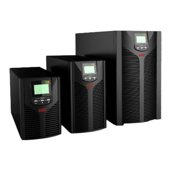
1.2 Product appearance (1-10KVA) 1.3 Product features ◆DSP digital control, full digital control of rectification and inversion; ◆High-frequency IGBT rectification is employed for input rectification, with input power factor up to 0.99; ◆For single-phase series, input harmonic current is less than 6%, reducing the feedback interference of UPS and relatively energy-saving;... - Page 6 type; ◆Wider voltage range (100-300vac), under main power mode and full-load condition, input voltage LOSS point can be 140vac; ◆Better machine performance index. Under rated nonlinear load, the machine features the input power factor bigger than 0.98, input current harmonic distortion less than 6%, output voltage harmonic distortion less than 5%, and conversion efficiency bigger than 89% under main power mode and 86% under battery mode.
- Page 7 From bypass mode to main power mode <4ms ECO mode conversion power failure ≤10ms Main power full-load ≧ 1 % Overall efficiency Battery full-load ≧90% ECO mode ≧ Turn to bypass working mode after 10 min 105%~125% load; Turn to bypass working mode after 1min 125%~150% Over-load capacity load, with alarm prompt;...
-
Page 8: Brief Introduction Of Product Principle And Internal Structure
2.1 System functional block diagram As the single-input single-output UPS, the EA900II series UPS is in serial connection between the power distribution system and load. The system design is applicable to provide the clean and uninterrupted power for the load and power distribution system even the upper line end of the AC power is interfered. -
Page 9: Graphical Illustration For Product's Internal Architecture
As shown in the schematic circuit diagram, when under normal condition, the main power generates bus voltage through the PFC boost circuit, and then converts it into AC power for the load through DC/AC inverter circuit. When main power is under abnormal condition (exceeding UPS main power input range or power failure), the energy stored by the battery will provide DC voltage through DC boost circuit to the bus and convert DC bus voltage into AC voltage by inverter and then output the AC voltage. - Page 10 Intelligent network card slot Communication interface 智能网卡插槽 通讯介面 Surge protection socket 浪涌保护插座 TEL/MODEM/FAX 风扇 Maintenance baffle 维修挡板 地 Input protection switch 输入保护开关 输入电源 输出电源 Input power source Output power source 6-10KVA (Standard) 2.3.2 Description of the internal structure of 6-10KVA type...
- Page 11 RS232 interface board PFC boost board Input filter SOS power board INV inversion board Charging board Output filter 6/10KVA long backup type...
- Page 12 6/10KVA Standard type...
-
Page 13: List Of Pcb Board Inside Ups
2.4 List of PCB board inside UPS List of 6KVA PCB board Code Name of material Model C.41.7010000 Circuit board- input filter I/P EMI (for 6K/10K) C.41.7010001 Circuit board- input filter O/P EMI (6K) Circuit board- surge C.41.7140000 TVSS (1-3K sharing) protection board EA900II 6-10KVA SPS V4.0,AC/DC ip,... -
Page 14: Pcb Working Principle And Port Definition
3. PCB working principle and port definition 3.1 DSP control board Control board is mainly composed of a 16-digit DSP controller and peripheral operational circuit; principally responsible for sequential control and PWM computation as well as the display and communication. It is the core part of UPS. 3.2 Description of the signal end of main control board 3.2.1 Main control board CN618 Connect to LCD display board... - Page 15 EPO functional interface 3.2.3 Main control CN7 Special interface for burning program 3.2.4 Main control board CN11 PFC, DC, INV driving signal, connecting to power board CN1. 3.2.5 Main control board CN5...
- Page 16 Sampled signal, connecting to the power board CN2 3.2.6 Main control board CN2 Connect to RS232. 3.2.7 Main control board C Connect to the long-life charging board...
- Page 17 3.2.8 Main control board CN4 Reserved 3.2.9 Main control board CN3 Connect to the built-in SNMP card. 3.2.10 Main control board CN800 Burning power interface...
- Page 18 6. Description of control board circuit The control board can be used for main power voltage amplitude and frequency detection, inversion output voltage and frequency detection, battery voltage detection, BUS voltage detection, load detection and inversion inductive current detection. 1) Zero-crossing detection circuit As the main power and inverter employs the same zero-crossing detection circuit, the main power zero-crossing detection circuit is taken as the example.
- Page 19 2) Amplitude detection circuit As the main power and inverter employs the same amplitude detection circuit, the main power amplitude detection circuit is taken as the example. 3) BUS voltage detection circuit BUS voltage detection circuit is used to detect the DC current around positive and negative 350V, which is sent to the main board via dropping resistor, and the main board sends it via the following difference channel to DSP.
- Page 20 No further description is provided since the main power voltage amplitude and frequency detection, inversion output voltage and frequency detection, battery voltage detection, BUS voltage detection, load detection and inversion inductive current detection are mostly identical to each other.
-
Page 21: Power Board
3.4 Power board SCR driver module board 6/10KVA PFC boost board... - Page 22 To PFC boost board STS driver module board INV driver module baord INV inversion board Main power sections of the power board: 1. Include the DC boosting, main power PPC boosting, DC filter, inversion output and bypass. 2. PFC, NV driver module (PFC is identical to the INV driver module), battery DC boosting module, SPS power module, fan detection module and charging module (standard type power board).
-
Page 23: Description Of The Signal End Of Power Board
Definition of power factor Power factor refers to the ratio of active power to apparent power. PF=P/(VRMS*IRMS) Two reasons may affect the power factor: first, the phase difference between voltage and current. If voltage and current is a standard sine wave, PF=COSθ, of which, θ means their phase difference;... - Page 24 •...
- Page 25 3.4.3 Port of fan module Fan module port signal Control of FAN • Functions of fan control module: • ①Achieve four-speed control for the fan according to the load magnitude: • LOAD>70% FANSPD DUTY=1 • LOAD>50% FANSPD DUTY=0.67 • LOAD>25% FANSPD DUTY=0.34 •...
- Page 26 •②Provide FANCLK SIGNAL for CPU to detect fan speed. • 1). Regulation of fan speed • •Analyze the relation between FANSPD signal and fan speed: • LOAD<25% FANSPD DUTY=0, average voltage on both ends of fan: 12V-3.3V=8.7V; • LOAD>25% FANSPD DUTY=0.34, average voltage on both ends of fan: 12V-3.3×(1-0.34)=12V-2.178V=9.822V;...
- Page 27 IGBT driver module (including PFC, INV)
- Page 28 6-10KVA SPS power board...
-
Page 30: Long Backup Type Charging Board
BAT battery terminal REC+ HFWP signal 3.5 Long-life charging board 3.5.1 Main power passes through the input end of long time-delay charging board and the input filter, then charge the long time-delay external battery. It is equipped with main power high-voltage protection, charging output high-voltage protection, providing SPS power for power board consistent to the charging power. - Page 31 3.5.3 Charging mode: 3.1 Three-stage charging mode: The first stage: recharge the batter with 90% capacity Constant power and marginal current: Charger’ s power is ≧3 hrs, recharge battery until full-load, discharge 5min, with 90% of capacity; When battery voltage reaches 13.9V/6 cells (F/W detection value error: n*(13.85V~13.95V), n;...
- Page 32 Series connection > Series connection ≦10 Pcs Pcs(Regulated By VR) High-voltage range (14.05~14.7V/6 cells) (14.3~14.4V/6 cells) Low-voltage range (13.26~13.8V/6 cells) (13.3~13.4V/6 cells) F/W high-voltage 13.9 V 13.9V timing voltage value When series connection ≦10 Pcs, voltage range is quite large, the existing charging voltage requires no VR regulation, controled under ±2%;...
-
Page 33: Ea900Ii Series Ups Installation, Switch And Precautions
3.5.2 For Battery Test, turn the charger ON after every 10 Sec discharging; stop discharging when voltage is lower than 10.5V, judge the battery NG. It can be carried out as per the demand of customer. 4. EA900II series UPS installation, switch and precautions 4.1 Selection of environment ·Working temperature: 0-40℃... - Page 34 Altitude: 1500m, meeting the requirement of GB3859.2-93 for sub-rating Verticality: no vibration and jolt, vertical gradient not exceeding 5 degrees. UPS system should be installed in a clean, cool and dustless environment with excellent ventilation and adequate humidity. Recommended working temperature: 20~25℃, humidity: Around 50%;...
- Page 35 UPS machine room should be equipped with professionals for management, and unauthorized personnel are not allowed to enter UPS machine room. 4.3 Unpack inspection 4.3.1 Unpack inspection ●Unpack UPS package and inspect the supplied accessories. Accessories should include a manual, communication line and disk. A battery connecting line shall be equipped for the long backup type.
- Page 36 UPS power system is equipped with the bypass power input neutral line and UPS power output neutral line. For three-in one-out UPS, the sectional area of its input zero line should be 1.5-1.7 times of the phase-conductor cable. UPS power system is also equipped with the protective earth wire and lightning protection earth wire, with sectional area 0.5-1.0 times of the phase-conductor cable, but no less than 6mm 4.4.1 Selection of air switch Output...
- Page 37 4.6 Battery connection EA900II series UPS is designed with 14 PCS battery connected in series, user can select the number of battery group and battery according to the actual condition, with connection pattern as shown below: UPS terminal block Battery switch...
- Page 38 ●For 6-10KVA battery is equipped with open-type connection line for connecting to battery group. Please strictly follow the following battery connection procedures since failure to comply with the procedure may cause electric shocking: ◇Connect battery group in serial to ensure proper battery voltage. ◇Batter connecting line should be first connected to the battery end (connecting to UPS end first may cause electric shocking), with red line connecting to anode “+”...
- Page 39 shocking. ●Place UPS near the main power input socket so as to unplug it to power off in case of emergency. Notice: ●It is required to shut down load prior to connecting the load to UPS, after connection, start up loads in sequence.
-
Page 40: Description Of Ups Panel Function And Mode Setting
② After shutdown, LED lamps will be out, no output. If needing output, user can set bpS under the setting interface as OK. Shut down UPS DC without main power ①Shut down machine by continuously pressing on the shutdown combination key more than half a second. - Page 41 5.1 Key function Startup combination key ( Execute the startup operation by pressing down the startup combination key more than half a second. Shutdown combination key ( Execute the UPS startup operation by pressing down the shutdown combination key more than half a second. System self-checking/silence combination key ( With a long press more than 1s under the main power or economy mode: UPS self-checking operation...
- Page 42 Under non-functional setting mode: A long press more than 2s: enter the function setting interface. Under the function setting mode: Short press more than half a second but less than 2s: confirm the setting option. Long press more than 2s: exit the function setting interface. 5.2 Functions of LED indicator light The inverter light, battery light, and bypass light and alarm light lies respectively from left to right.
- Page 43 LCD panel display Graphic display area: 1) The load and battery represents the load and battery capacity, 25% for each square. When UPS is overloaded, the load icon will flash, and the battery icon will flash when battery capacity is too low or the battery is not connected; 2) Fan icon represents its working status.
- Page 44 2) Under setting mode, it is able to set output voltage value and activate the bypass and eco mode by operating the function setting key and the left/right query key. Power grade and working mode display area: 1) Within 20s after startup, the display area will mainly display the power grade of the machine;...
- Page 45 ① Enter the setting interface with a long press more than 2s on the setting , and then the character “ECO” will flash. ②Enter the ECO setting interface with a short press more than half a second but less than 2s on the setting key , the character “ECO”...
- Page 46 setting key ; with a short press more than half a second but less than 2s on the query key , user can select the function setting and bypass output setting interface, then the character “bPS” will flash. ②Enter the bPS setting interface with a short press more than half a second but less than 2s on the setting key , the character “bPS”...
- Page 47 Output voltage setting interface ①Enter the setting interface with a long press more than 2s on the function setting key ; With a short press more than half a second but less than 2s on the query key , user can select the function setting; after selecting the output voltage setting interface, the character “OPU”...
- Page 48 ④After a long press more than 2s on the setting key , exit the setting interface, back to the main interface and display the UPS output information. 5.7 Parameter query Check the information relating to input, battery, output, load and temperature with a short press more than half a second but less than 2s on the query key After a long press more than 2s on the right query key , LCD will display...
- Page 49 Note: under no-load condition, it is quite normal for LCD to display the smaller load value. Temperature: display the maximum temperature point of the internal components, as shown below Input: display the input voltage and frequency, as shown below: Battery: display the battery voltage and capacity, as shown below:...
-
Page 50: Description Of Ups Working Mode
6. Description of UPS working mode 6.1 Bypass mode Under bypass mode, LED indicators are shown as below (white means the illuminate status), in addition, under LCD mode, the display area will display the character “Bypass”. When bypass LED yellow light is illuminated, buzzer will sound every 2min accompanied by the illuminated alarm LED red light. - Page 51 6.3 Battery mode LED indicators are shown as blow under the battery mode: constantly illuminated inverter LED green light and battery LED yellow light, buzzer alarms every 4s, LED red alarm light is illuminated, and the character bat is displayed in the display area under LCD mode. During battery self-checking, the inverter light, bypass light, battery light and fault light will flash in cycles, and the character batt is displayed in the display area under LCD mode.
-
Page 52: List Of Led And Lcd Display Alarms
is constantly illuminated, in addition, the fault icon and code will be displayed in the display area under LCD mode. In case of UPS fault, alarm light will be constantly illuminated and buzzer sounds. For instance, the overload fault, inversion fault and over-temperature fault, UPS will enter the fault mode, stop output and display the fault code with LCD. - Page 53 Output 45-49 short-circuit Overload 50-54 Input NTC fault 55-59 Power fault 60-64 Input fuse 65-69 fault Others Appendix I: Corresponding working status for displays Panel light signal display Working status Alarm sound Remark Normal Battery Bypass Fault Main power inversion mode Normal main power ●...
- Page 54 Warning for battery disconnection buzzing Under bypass status ● every four ★ seconds One buzzing Under inversion ● every four ★ status seconds Power on or start up Six buzzing Input overload protection buzzing Overload under main ● ★ every power mode, warning second Overload under main...
-
Page 55: Troubleshooting
◇Complete description (including panel indicator light display, sound, power, load capacity; for long backup type, battery equipment information should also be provided). 8. Troubleshooting LCD indications under fault mode are shown as below: Fault display Fault code Troubleshooting for abnormal conditions Faults Causes Solutions... - Page 56 constantly illuminated, buzzer constantly sounds, with fault code 25-39. Ensure no UPS overload, no Fault indicator light is vent blockage and excessive constantly illuminated, Internal high indoor temperature. Wait buzzer constantly sounds, over-temperature 10min to allow UPS cool down, with fault code 40-44 restart it, if failed, contact with your supplier.
- Page 57 buzzer constantly sounds, with fault code 55-59 Fault indicator light is Find out the power part, check constantly illuminated, the power input and output, if Power fault buzzer constantly sounds, any abnormal condition were with fault code 60-64 found, contact your supplier. Fault indicator light is Inspect the input fuse for constantly illuminated,...
- Page 58 Internal fault of UPS Contact with your supplier. UPS should be connected to the Battery main power in three consecutive undercharged hours, and recharge the battery. Short battery discharge Check the load capacity and UPS overload time remove non-critical equipments. Replace battery, and contact Aging battery with your supplier for the battery and...
- Page 59 PCB01.PCB02 positive and negative UBS voltage detection module Connecting to fan PCB04.PCB05 module PCB06 power Mutual inductor at PFC detection boost part PCB07 battery detection BUS absorption circuit BAT- input relay PFC boost inductor Battery fuse PCB10BAT-SCR driver module PCB09 main power –SCR driver module Main power zero and live line...
- Page 60 Inversion inductive current detection DC BUS filter capacitor Output filter inductor Output filter capacitor Inverted RCD absorption circuit STS part circuit Output relay PCB1.PCB4 INV driver module...
- Page 61 1. Working power generates circuit (See the following figure) A. Common fault handling Fault Multimeter Standard Fault Fault value component gear value Resistor gear 0 or too low U1(6-5) 47 KΩ Diode gear interelectrode Around 0.37V Resistor gear —— Infinite No power 47 Ω...
- Page 62 Note: 6-10KVA long-life charging board input terminal operates from the REC part of power board PFC main power. After passing through BUCK circuit, the output voltage is DC168V (floating charge voltage is 196V). SCR-Q10 is a “suicide” circuit, SCR-Q10 will be on and its fuse F1-F2 will be burned out for protection when detecting excessive high output.
- Page 63 2. Output voltage feedback regulation:...
- Page 64 A. Charging board Reference Fail Item Checked components function Value Condition FUSE open Ω Ω ≈1M (E,C) short Ω Ω short or (G,E) Ω Ω open ≈0.4V DIODE R315 open Ω Ω R319 open Ω Ω ≈0.4V D09,D7 DIODE R112 , R159 open Ω...
- Page 65 Fail Reference Item Checked components Condi Function Value tion ≈800k (E, C) short Q306, Q308、 Ω Ω Q310 short Q307, Q309、 15.8k (G, E) Ω Ω Q311 open ≈0.35V D308, D310 DIODE R325, R331, R334, R342, open Ω Ω R337, R328 R390, R388, R389, R393, open Ω...
- Page 66 Power board PSDR B: INV part: 1. The inverter part includes the main circuit inverter, inversion IGBT tube voltage drop protection, inductive current detection and RCD absorption circuit.
- Page 67 2. Include STS conversion (conversion between bypass and inversion, SCR’s compensation and conversion time is 0ms) load detection, after inductive current detection signal is sent to the main board DSP. Reference Fail Item Checked components Function Value Condition ≈2.5M (A, K) short Ω...
- Page 68 (B-4). Inverter part: Reference Fail Item Checked components Function Value Condition ≈100k Q1, Q2, (E, C) short Ω Ω Q3,Q4 23.5k (G, E) short or open Ω Ω D2, D3, D4.D7, D5, D6, D13.D14 ≈0.36V DIODE R13, R16, R49, R52 open Ω...
- Page 69 Voltage wave form (V ) between C and E polarity of PFC IGBT under no-load condition...
- Page 70 Driving voltage wave form (V ) at G and E of IGBT Voltage wave form (V ) between C and E polarity of PFC IGBT Note: precautions for maintenance 1. Current limit startup Current limit startup is required after maintenance or replacement of board. To prevent serious fault, it is forbidden to start up at will.
-
Page 71: Precautions For Battery Handling
2) Start up machine, observe and check signal, working power, positive and negative BUS voltage (±350VDC) and output voltage. In such case, it should work under no-load condition; 3) After it is normally started, connect to the main power and complete the corresponding measurements;... - Page 72 ◇Inspect battery for voltage prior to touch. There will be high voltage between the battery terminals and the ground if the battery loop and input voltage loop is not isolated. 10. Network communication EA901II~9010II (1KVA~10KVA) provides intelligent network card interface, and allows for the UPS network communication by combining the special Ethernet card (optional accessories).
- Page 73 ◇Character length: 8bit ◇End code: 1bit ◇Parity bit: None...
Need help?
Do you have a question about the EA900II Series and is the answer not in the manual?
Questions and answers