
Related Manuals for East EA990G5


Summary of Contents for East EA990G5
- Page 1 EA990G5 10-30kVA (3/3) Maintenance Manual Prepared by Wu Zhifei / 20220830 Checked by Luo Changsheng / 20220831 Approved by Yang Lin / 20220831 EAST GROUP CO., LTD.
- Page 2 Preface General This document provides maintenance requirement for high frequency three-input single-output 6-20KVA products, including safety precautions for maintenance, product description, description on internal structure, description on composition of single boards, main components of single boards, description on main functions, fault removal flow, replacement of single boards, maintenance of single boards, and commissioning after maintenance, etc., to help an engineer to provide technical support and maintenance service for three-input single-output 6-20K products.
-
Page 3: Table Of Contents
2 Description of model........................2 2.1 Description of EA990G5 10-30kVA serial model..............2 2.2 Appearance introduction of EA990G5 10-30kVA series model..........3 2.3 The operation control LCD panel introduction of EA990G5 10-30kVA........ 6 3 Internal Introduction........................23 3.1 System Configuration......................23 3.2 System Block Diagram......................26 3.3 Introduction to Internal Boards..................... - Page 4 7.1 Boards installation......................... 72 7.2 Preparation before power-on....................72 7.3 Power-on and testing......................72...
-
Page 5: Safety Precautions
1 Safety precautions 1.1 Hazards 1.As dangerous voltage exists in the UPS and the battery holder, installation and maintenance are only completed by a professional engineer holding professional electrician qualification of the company or authorized by the company. 2.Operators and maintainers, and professional technicians should receive full training on safe use and equipment maintenance and work on the equipment after enough precautionary measures are taken and personal safety equipment is used. -
Page 6: Description Of Model
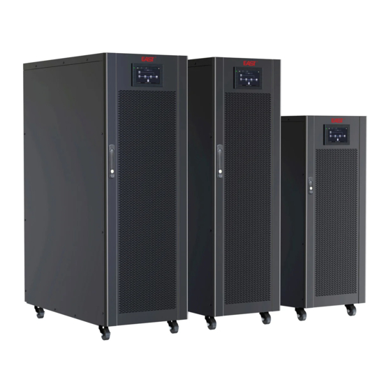
2.1 Description of EA990G5 10-30kVA serial model Our EA990G5 10-30kVA series models are divided into tower type and rack type. The power level is 10/15/20/30KVA and the output power factor is 1.0. It can realize parallel operation of up to 4 units, provide redundant power supply, and provide stable and reliable power supply for customer loads. -
Page 7: Appearance Introduction Of Ea990G5 10-30Kva Series Model
UPS. 2.2 Appearance introduction of EA990G5 10-30kVA series model The overall appearance is shown in Figures 2-1 to 2-7 below. Fig.2-1 The front pannel of 10-30kVA series UPS (Tower) - Page 8 Fig.2-3 The rear pannel of 10kVA, 15kVA, 20kVA long-delay UPS (Tower) Fig.2-4 The rear pannel of 10kVA, 15kVA, 20kVA standard UPS (Tower)
- Page 9 Fig.2-5 The rear pannel of 30kVA UPS (Tower) Fig.2-6 The rear pannel of 10kVA, 15kVA, 20kVA UPS (Rack)
-
Page 10: The Operation Control Lcd Panel Introduction Of Ea990G5 10-30Kva
Terminal block and cover Battery breaker 2.3 The operation control LCD panel introduction of EA990G5 10-30kVA This chapter introduces the functions and operator instructions of the operator control and display panel in detail, and provides LCD display information, including LCD display types, detailed menu information, prompt window information and UPS alarm information. - Page 11 Fig.2-8 Control and display panel LED Indicator There are 2 LEDs on the panel to indicate the operating status and fault.The description of indicators is shown in table 2-4。 Table 2-4 Status description of indicators Indicators State Description Steady red UPS fault Flashing red UPS alarming...
- Page 12 Fig.2-9 Menu 2.3.2 Home page After the monitoring system starts self-test, the system enters the home page, following the welcome window. The home page is divided into three parts, including main menu, energy flow diagram, status bar. The home page is shown in Fig. 2-10. Fig.
- Page 13 Area Function description Energy flow diagram Display the energy flow state of the cabinet. Click the corresponding work interface to view the status information. Status bar Display operation status, system time, buzzer status, alarm status, HMI and monitoring communication status, USB status of the cabinet.
- Page 14 Fig. 2-11 Input interface Table 2-9 Description of input interface Display item Description Voltage (V) Mains input phase voltage Current (A) Mains input phase current Frequency (Hz) Mains input frequency Mains input Power factor Bypass The menu interface of the bypass input is shown in Fig. 2-12, and the interface description is shown in Table 2-10.
- Page 15 Display item Description Current (A) Bypass input phase current Frequency (Hz) Bypass input frequency Bypass input Power factor Battery The interface menu of battery input is shown in Fig. 2-13, and the interface description is shown in Table 2-11. Fig. 2-13 Battery interface Table 2-11 Description of battery interface Display item Description...
- Page 16 Fig. 2-14 Output interface Table 2-12 Description of output interface Display item Description Voltage (V) AC output phase voltage. Current (A) AC output phase current. Frequency (Hz) AC output frequency. Load ratio (%) Load rate of each phase of the machine Active power (kW) Output active power of each phase of the UPS unit Appa.
- Page 17 Table 2-13 Description of other interface Display item Description PFC temperature Rectifier temperature INV temperature Inverter temperature Environmental Environmental temperature(optional battery temperature sensor, temperature display "NA" if not connected) Statistics The interface of statistics menu is shown in Fig. 2-16, and the interface description is shown in Table 2-14. Fig.
- Page 18 Fig. 2-17 About interface Table 2-15 Description of Interface Display item Description Production serial number of this machine. Contact information of after-sales service providers. Manufacturer Manufacturer of this machine. Website Website of manufacturer of this unit. HMI version Program version of HMI display system. PFC1 version Program version of power rectifier system Inv.1 version...
- Page 19 Active alarm The active alarm interface displays the relevant information of the current warning of UPS system, The interface description is shown in Table 2.16. Table 2-16 Description of active alarm interface Display item Description Alarm number Location Display the cabinet number and module number of the current alarm source.
- Page 20 4.2.6 Control In the "Control " information interface, you can select relevant operation from the left secondary menu, which contains "On-Off "and "Maintain". On-Off The interface of the On-Off menu is shown in Fig. 2-20, and the interface description is shown in Table 2-18. Fig.
- Page 21 Fig. 2-21 Maintenance interface Table 2-19 Description of maintenance interface Control item Description Mute Mute the buzzer Clear history Clear history Faults Clear Clear the fault Bat Test1 UPS transfer to battery discharge mode to test if the battery is normal. Bypass must be in normal condition, the battery capacity should be above 25%.
- Page 22 Fig. 2-22 Common setting interface Table 2-20 Description of common setting interface Setting item Default Options Description Language English English Display in English. YYYY-MM-DD 2016-01-01 2000-01-01~2099-12-31 Set the current date. Time 00:00:00 00:00:00~23:59:59 Set the current time. Support 3 formats: Y-M-D, M-D-Y, Date format Y-M-D Y-M-D, M-D-Y, D-M-Y...
- Page 23 Table 2-21 Description of communication settings interface Dry contact settings The interface of dry contact setting menu is shown in Fig. 2-24, and the interface description is shown in Table 2-22. Fig. 2-24 Dry contact setting interface Table 2-22 Description of dry contact setting interface INTERFACE Name Function...
- Page 24 Fig. 2-25 Bypass parameters interface Table 2-23 Description of bypass parameters interface Setting item Default Options Description Battery type: VRLA battery and Lithium battery, Lithium/VRL Batt.Type VRLA The supported lithium battery type is 3.2 V lithium iron phosphate battery. Rate output freq 50/60 Rate output frequence Rate output...
- Page 25 Table 2-24 Description of advanced parameters interface Setting item Default Options Description Select the corresponding working mode Normal/ECO/Self-ag Working mode Normal according to user needs. It is normal e/ Parallel mode working mode in general. Set according to the actual frame numbers Parallel Number 1 1 ~ 4 of the UPS system installed by the user.
- Page 26 Setting item Default Options Description et according to the total number of battery cells connected Battery to the UPS system, each conventional lead-acid battery settable number has 6 battery cells, for example, 32 batteries × 6=192 battery cells. Battery capacity settable Single battery capacity connected to the UPS system.
-
Page 27: Internal Introduction
3 Internal Introduction 3.1 System Configuration The Tower UPS is configured by the following part: Rectifier, Charger, Inverter, Static Switch and Manual Bypass Switch. One or several battery strings should be installed to provide backup energy once the utility fails. The UPS structure is shown in Fig. - Page 28 Battery Mode Upon failure of the AC mains input power, the inverter of power modules, which obtain power from the battery, supply the critical AC load. There is no interruption in power to the critical load upon failure. After restoration of the AC mains input power, the “Normal mode” operation will continue automatically without the necessity of user intervention.
- Page 29 Maintenance Mode (Manual Bypass) A manual bypass switch is available to ensure continuity of supply to the critical load when the UPS becomes unavailable e.g. during a maintenance procedure. (As shown in Fig.3-5). Fig .3-5 Maintenance mode operation diagram Danger During Maintenance mode, dangerous voltages are present on the terminal of input, output and neutral, even with the LCD turned off.
-
Page 30: System Block Diagram
It needs only 5% loss to burn in UPS with 100% load. Fig.3-7 self aging operation diagram 3.2 System Block Diagram The system block diagram of EA990G5 10-30kVA is shown as Fig.3-8. Fig.3-8 System Block Diagram... -
Page 31: Introduction To Internal Boards
3.3 Introduction to Internal Boards Table 3-1 Internal Boards introduction of EA990G5 10-30kVA Board name PCBA Code Introduction Remark Including input filter circuit, mains 10kVA IP/OP 12-202700-00 soft-start circuit, output filter circuit, board auxiliary power supply and charger 10kVA Power... -
Page 32: Troubleshooting
4 Troubleshooting This chapter mainly introduces all the alarm information of the system, the meaning of the alarm, the possible cause of the alarm, and the processing method. 4.1 Repair tool List Table 4-1 Repair tool list Tools Number Remark Oscilloscope Measurement waveforms Measure voltage and resistance,... - Page 33 1. Fault record of UPS: The first on-site information of the fault is very important. According to these information, the fault point and the cause of the fault can be roughly judged, and the correct solution can be formulated. Therefore, the first thing for engineers to arrive at the site is to record all the conditions of the power system, mainly recording the following: 1) The status of the UPS system (panel and monitoring information): the information of each display interface of the LCD screen when a fault occurs, and the display status of the UPS on the monitoring side;...
-
Page 34: Alarm Information Collection
4.3 Alarm information collection 4.3.1 LCD screen alarm information collection When the maintenance personnel arrive at the scene for the first time, the alarm information needs to be collected as soon as possible in order to obtain an effective basis for fault analysis. Record the display conditions of the LCD panel (mainly fault codes) in detail, and record the working conditions of the LED indicators. - Page 35 1. Check whether the mains input air The effective value of the three-phase switch is disconnected; Grid input breaker open input voltage is lower than 35% 2. Check whether the mains input insurance is damaged; UPS maintenance breaker Maintenance bypass closed signal Check whether the maintenance close trigger...
- Page 36 Check whether the phase sequence of Input phase sequence error input reversed the mains input voltage is reversed Check whether the mains input Input phase loss Input missing 1 or 2 phases voltage is abnormal The difference between the maximum Check whether the mains input Input voltage imbalance and the lowest input voltage is 17V...
- Page 37 The charger voltage is 10V higher Charger overvoltage Please replace the I/O board than the equalizing voltage Charger voltage is lower than 80% of Charger undervoltage Please replace the I/O board battery voltage The bus voltage continuously drops Bus-bar short circuit Please replace the power board more than 150V in 3ms Bus-bar overvoltage...
- Page 38 1. Check whether the parallel cable Parallel operation wire Parallel operation wire abnormal connection is normal; abnormal 2. Replace the parallel line; Inverter radiator Inverter temperature is higher than 80 Please check whether the fan is overtemperature degrees abnormal; Inverter E2PROM operation Inverter E2PROM read and write Please replace the I/O board failure...
-
Page 39: Board Replacement
5 Board replacement 5.1 Board replacement of 10kVA model The 10kVA model includes the following boards: power board, IP/OP board, bypass board, monitoring board, cold start board, parallel interface board, communication interface board, dry contact board; the specific locations are shown in Fig.5-1 to 5-5. Fig.5-1 The right side board of 10kVA long-delay model (Tower) Fig.5-2 The left side board of 10kVA long-delay model (Tower) - Page 40 Fig.5-3 The right side board of 10kVA standard model (Tower) Fig.5-4 The left side board of 10kVA standard model (Tower)
-
Page 41: Board Replacement Of 15Kva Model
Fig.5-5 The board of 10kVA model (Rack) 5.2 Board replacement of 15kVA model The 15kVA model includes the following boards: power board, IP/OP board, bypass board, monitoring board, cold start board, parallel interface board, communication interface board, dry contact board; the specific locations are shown in Fig.5-6 to 5-10. - Page 42 Fig.5-7 The left side board of 15kVA long-delay model (Tower) Fig.5-8 The right side board of 15kVA standard model (Tower)
- Page 43 Fig.5-9 The left side board of 15kVA standard model (Tower) Fig.5-10 The board of 15kVA model (Rack)
-
Page 44: Board Replacement Of 20Kva Model
5.3 Board replacement of 20kVA model The 20kVA model includes the following boards: power board, IP/OP board, bypass board, monitoring board, cold start board, parallel interface board, communication interface board, dry contact board; the specific locations are shown in Fig.5-11 to 5-15. Fig.5-11 The right side board of 20kVA long-delay model (Tower) Fig.5-12... - Page 45 Fig.5-13 The right side board of 20kVA standard model (Tower) Fig.5-14 The lest side board of 20kVA standard model (Tower)
-
Page 46: Board Replacement Of 30Kva Model
Fig.5-15 The board of 20kVA model (Rack) 5.4 Board replacement of 30kVA model The 30kVA model includes the following boards: power board, IP/OP board, Inductor board, bypass board, monitoring board, cold start board, parallel interface board, communication interface board, dry contact board; the specific locations are shown in Fig.5-16 to 5-20. - Page 47 Fig.5-17 The left side board of 30kVA long-delay model (Tower) Fig.5-18 The right side board of 30kVA standard model (Tower)
- Page 48 Fig.5-19 The left side board of 30kVA standard model (Tower)
-
Page 49: Board Maintenance
6 Board maintenance Maintenance of EA990 G5 10-30kVA series UPS requires maintenance engineer having basic circuit theory, power electronics related knowledge, and knowledge of related circuit topology. In addition, the improvement of maintenance skills requires the accumulation of long-term maintenance experience. Please keep a good record of maintenance notes during the maintenance process. - Page 50 Fig.6-1 Key components identification of 10kVA power board The detailed maintenance steps are as follows: Step 1: Check whether the copper foil is corroded and rusted on the whole power board. You can use a multimeter to assist in the inspection. If there is corrosion, the copper foil needs to be re-soldered. Step 2: Visually inspect the entire power board for obvious burns or cracks, and replace if necessary.
- Page 51 After completing the inspection work in steps 1-6, replace the damaged device; after replacing the device, use the shorting cap to short-circuit J2 of the rectifier control board CT1 and J2 of the inverter control board CT2, and then follow the steps shown in Figure 6-2. Connection method Connect the main power board to the input and output board (only connect the signal cable, not the copper bus), and carry out the drive test.
- Page 52 High level +15V±1V; Low level Inverter inner bridge IGBT Q9,Q10,Q13,Q14,Q17,Q18 -8V±1V; Frequency 20KHz; High level 1V-1.5V; Battery SCR S7,S8,S9,S10,S11,S12 Low level 0V; If it is found that the individual IGBT or SCR drive is abnormal during the drive test, please re-check whether the device is replaced, and check whether the corresponding drive module is damaged.
- Page 53 ZD17,ZD18,ZD19,ZD20,ZD21, ZD22,ZD23,ZD24,ZD25,ZD26, ZD27,ZD28,ZD29,ZD30,ZD31, ZD32,ZD33,ZD34,ZD35,ZD36, ZD37,ZD38,ZD39,ZD40,ZD41 Boost diode D1,D2,D3,D4,D5,D6 RHRP3060 MM30FU60K Fig.6-3 Key components identification of 15kVA power board The detailed maintenance steps are as follows: Step 1: Check whether the copper foil is corroded and rusted on the whole power board. You can use a multimeter to assist in the inspection.
- Page 54 Step 5: Use the diode gear of the multimeter to test the input rectifier diode and Boost diode. If the forward voltage drop is too low (less than 0.1V) or there is also a reverse voltage drop, the diode may be damaged and needs to be replaced.
- Page 55 High level +15V±1V; Low level Inverter outer bridge IGBT Q7,Q8,Q11,Q12,Q15,Q16 -8V±1V; Frequency 20KHz; High level +15V±1V; Low level Inverter inner bridge IGBT Q9,Q10,Q13,Q14,Q17,Q18 -8V±1V; Frequency 20KHz; High level 1V-1.5V; Battery SCR S7,S8,S9,S10,S11,S12 Low level 0V; If it is found that the individual IGBT or SCR drive is abnormal during the drive test, please re-check whether the device is replaced, and check whether the corresponding drive module is damaged.
- Page 56 Table 6-5 The fragile componments of 20kVA power board Components Tag Number Specifications Alternative specification S1,S2,S3,S4,S5,S6,S7,S8,S9,S10,S11, Battery SCR VS-50TPS12L-M3 CLA50E1200HB Battery driver PCB10,PCB11 module Boost IGBT Q1,Q2,Q3,Q4,Q5,Q6 IKW50N65H5 MM75G5U65BX Inverter outer bridge Q7,Q8,Q11,Q12,Q15,Q16 IKW40N120CS6 MM40G3U120BX IGBT Inverter inner bridge Q9,Q10,Q13,Q14,Q17,Q18 IKW30N65EL5 JT050N065WED IGBT...
- Page 57 Step 3: Use the diode gear of the multimeter to detect the PIN1(+)-PIN3(-) and PIN2(+)-PIN3(-) of the boost IGBT and the inverter outer/inner bridge IGBT. If the multimeter shows that the voltage drop is too low (less than 0.1V), you need to replace the corresponding IGBT. Note: When replacing the IGBT, it is necessary to apply heat dissipation paste on the back of the IGBT.
- Page 58 High level +15V±1V; Low level Boost IGBT Q1,Q2,Q3,Q4,Q5,Q6 -8V±1V; Frequency 40KHz; High level +15V±1V; Low level Inverter outer bridge IGBT Q7,Q8,Q11,Q12,Q15,Q16 -8V±1V; Frequency 20KHz; High level +15V±1V; Low level Inverter inner bridge IGBT Q9,Q10,Q13,Q14,Q17,Q18 -8V±1V; Frequency 20KHz;...
- Page 59 High level 1V-1.5V; Main and battery SCR S1,S2,S3,S4,S5,S6,S7,S8,S9,S1 0,S11,S12 Low level 0V; If it is found that the individual IGBT or SCR drive is abnormal during the drive test, please re-check whether the device is replaced, and check whether the corresponding drive module is damaged. 6.1.4 Board replacement of 30kVA model The 20kVA power board is mainly divided into a rectifier booster part and an inverter part.
- Page 60 Fig.6-7 Key components identification of 30kVA power board The detailed maintenance steps are as follows: Step 1: Check whether the copper foil is corroded and rusted on the whole power board. You can use a multimeter to assist in the inspection. If there is corrosion, the copper foil needs to be re-soldered. Step 2: Visually inspect the entire power board for obvious burns or cracks, and replace if necessary.
- Page 61 After completing the inspection work in steps 1-6, replace the damaged device; after replacing the device, use the shorting cap to short-circuit J2 of the rectifier control board CT1 and J2 of the inverter control board CT2, and then follow the steps shown in Figure 6-8. Connection method Connect the main power board to the input and output board (only connect the signal cable, not the copper bus), and carry out the drive test.
-
Page 62: Maintenance Of Ip/Op Board
High level +15V±1V; Low level Inverter inner bridge IGBT Q9,Q10,Q13,Q14,Q17,Q18 -8V±1V; Frequency 20KHz; High level 1V-1.5V; Main and battery SCR S1,S2,S3,S4,S5,S6,S7,S8,S9,S1 0,S11,S12 Low level 0V; If it is found that the individual IGBT or SCR drive is abnormal during the drive test, please re-check whether the device is replaced, and check whether the corresponding drive module is damaged. - Page 63 Fig.6-9 The key components identification of 10kVA IP/OP board The detailed maintenance steps are as follows: Step 1: Check whether the copper foil is corroded and rusted on the entire I/O board. You can use a multimeter to assist in the inspection. If there is corrosion, the copper foil needs to be re-soldered. Step 2: Visually inspect the entire I/O board for obvious burns or explosions, and replace if necessary.
- Page 64 and then follow the steps shown in Figure 6-10. Connection method for drive test. The test waveforms of each key device are shown in Table 6-10. Fig.6-10 The connection of drive test circuit of 10kVA IP/OP board Table 6-10 The driver test description of 10kVA IP/OP board Component and its tag number Waveform Remark...
- Page 65 Fig.6-11 The key components identification of 15kVA IP/OP board The detailed maintenance steps are as follows: Step 1: Check whether the copper foil is corroded and rusted on the entire I/O board. You can use a multimeter to assist in the inspection. If there is corrosion, the copper foil needs to be re-soldered. Step 2: Visually inspect the entire I/O board for obvious burns or explosions, and replace if necessary.
- Page 66 and then follow the steps shown in Figure 6-12. Connection method for drive test. The test waveforms of each key device are shown in Table 6-12. Fig.6-12 The connection of drive test circuit of 15kVA IP/OP board Table 6-12 The driver test description of 15kVA IP/OP board Component and its tag number Waveform Remark...
- Page 67 Fig.6-13 The key components identification of 20kVA IP/OP board The detailed maintenance steps are as follows: Step 1: Check whether the copper foil is corroded and rusted on the entire I/O board. You can use a multimeter to assist in the inspection. If there is corrosion, the copper foil needs to be re-soldered. Step 2: Visually inspect the entire I/O board for obvious burns or explosions, and replace if necessary.
- Page 68 and then follow the steps shown in Figure 6-14. Connection method for drive test. The test waveforms of each key device are shown in Table 6-14. Fig.6-14 The connection of drive test circuit of 20kVA IP/OP board Table 6-14 The driver test description of 20kVA IP/OP board Component and its tag number Waveform Remark...
- Page 69 Fig.6-15 The key components identification of 30kVA IP/OP board The detailed maintenance steps are as follows: Step 1: Check whether the copper foil is corroded and rusted on the entire I/O board. You can use a multimeter to assist in the inspection. If there is corrosion, the copper foil needs to be re-soldered. Step 2: Visually inspect the entire I/O board for obvious burns or explosions, and replace if necessary.
-
Page 70: Maintenance Of Bypass Board
and then follow the steps shown in Figure 6-16. Connection method for drive test. The test waveforms of each key device are shown in Table 6-16. Fig.6-16 The connection of drive test circuit of 30kVA IP/OP board Component and its tag number Waveform Remark High level... - Page 71 Fig.6-17 The key components identification of 10kVA bypass board The detailed maintenance steps are as follows: Step 1: Check whether the copper foil is corroded and rusted on the entire I/O board. You can use a multimeter to assist in the inspection. If there is corrosion, the copper foil needs to be re-soldered. Step 2: Visually inspect the entire I/O board for obvious burns or explosions, and replace if necessary.
- Page 72 Table 6-18 The driver test description of 10kVA bypass board Component and its tag number Waveform Remark High level 1V-1.5V; Bypass SCR Q1,Q2,Q3,Q4,Q5,Q6 Low level 0V; If it is found that the individual SCR is abnormally driven during the drive test, please re-check whether the device is replaced, and check whether the corresponding drive module is damaged.
- Page 73 Step 1: Check whether the copper foil is corroded and rusted on the entire I/O board. You can use a multimeter to assist in the inspection. If there is corrosion, the copper foil needs to be re-soldered. Step 2: Visually inspect the entire I/O board for obvious burns or explosions, and replace if necessary. Step 3: Measure the resistance of the bypass thyristor (SCR) with the ohm gear of the multimeter.
- Page 74 Table 6-21 The frogile component of 30kVA bypass board Alternative Components Tag Number Specifications specification Bypass SCR Q1,Q2,Q3,Q4,Q5,Q6 VS-70TPSPBF Fig.6-21 The key components identification of 30kVA bypass board The detailed maintenance steps are as follows: Step 1: Check whether the copper foil is corroded and rusted on the entire I/O board. You can use a multimeter to assist in the inspection.
- Page 75 Table 6-20 The driver test description of 30kVA bypass board Component and its tag number Waveform Remark High level 1V-1.5V; Bypass SCR Q1,Q2,Q3,Q4,Q5,Q6 Low level 0V; If it is found that the individual SCR is abnormally driven during the drive test, please re-check whether the device is replaced, and check whether the corresponding drive module is damaged.
-
Page 76: Test
7 Test This chapter mainly introduces how to test the UPS after maintenance. 7.1 Boards installation After the maintenance of the abnormal board is completed, it needs to be installed on the whole machine for debugging to confirm whether the single board is fixed. Please install the repaired board on the whole machine according to the content in Chapter 5, and ensure that the installed position is correct and the wiring is correct. - Page 77 Step 6: 5 minutes after the UPS is completely powered off, re-close the battery pack air switch; press the cold start switch until the LCD screen of the UPS lights up (about 3seconds), and then click the "cold start" button on the screen to start the battery cold start.
Need help?
Do you have a question about the EA990G5 and is the answer not in the manual?
Questions and answers