
Related Manuals for East EA900IIRT 1000VA


Summary of Contents for East EA900IIRT 1000VA
- Page 1 MANUAL DE USUARIO UPS ON LINE DOBLE CONVERSION EAST EA900II RT DE 1000 – 3000 VA - 1 -...
-
Page 2: Safety Instructions
Please strictly obey all the instructions in this manual and pay attention to all the warning and operation information. It is not advisable to install or operate the machine before read this manual. 1. Safety Instructions ● The power outlet voltage may still have 220V even not connect to the mains power. ●... -
Page 3: Attention Items Of Installation
Note: Please save the packaging box and packaging materials for future transport use. As heavy product, please transit the UPS with care. 2.2. Attention items of installation ● The UPS location circumstance must be with good ventilation, away from water, flammable gases and corrosive entities. -
Page 4: Ups Output Connection
FUSE 250VAC,15A INPUT RESET OUTPUT SOCKET INTELLIGENT 48VDC 40A SLOT EXT.BATTERY Figure 2. 1.5KVA & 2KVA rear panel FUSE 250VAC,20A INPUT RESET OUTPUT SOCKET INTELLIGENT 72VDC 40A SLOT EXT.BATTERY Figure 3. 3KVA rear panel DC OUTPUT DC OUTPUT 72VDC 72VDC Figure 4. -
Page 5: External Battery Connection Procedure For Long Back Up Type
2.5 External battery connection procedure for long back up type ● As per different UPS type, end user are instructed to configure different battery voltage as below sheet. More or less units are forbidden or else something abnormal or faulty will appear. Type Battery Quantity (unit) Battery Voltage (volt) -
Page 6: Installation
FUSE 250VAC,15A INPUT RESET OUTPUT SOCKET INTELLIGENT 48VDC 40A SLOT EXT.BATTERY BLACK Figure 6. 1.5KVA &2KVA long back up connection FUSE 250VAC,20A INPUT RESET OUTPUT SOCKET INTELLIGENT 72VDC 40A SLOT EXT.BATTERY BLACK Figure 7. 3KVA long back up connection 2.6 Installation ●... -
Page 7: Panel Function And Operation
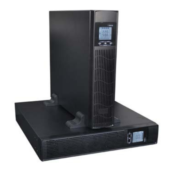
Installation steps: 1) Please take out two groups of supports, assemble by embedding them with each other as shown below. 2) Place the two supports in parallel, then put the machine into two supports. 3) It also can be placed horizontally if you like, please remember not to put the machine upside down. -
Page 8: Keys Function
3.1 Keys function Inverter LED Battery LED Bypass LED Warning LED 2 5 % 5 0 % 7 5 % 1 0 0 % OUTPUT 7 5 % 2 5 % 5 0 % 1 0 0 % ON/OFF ROTATE TEST/MUTE ※... -
Page 9: Led Function
After finish that, the machine can be placed flat, as shown in the picture below OUTPUT ※ INQUIRING key ( ) I. Non-function setting mode: 1) Press and hold for more than half a second (less than 2 seconds): display the items orderly. - Page 10 3.3 LCD display function LCD displays as following Figure. Icon display area O U T P U TLO A DT E MP IN P U T B A T T E R Y Battery capacity Load capacity display area ℃ display area Working mode display area...
-
Page 11: Turn On/Off Operation
3.4 Turn On/Off operation 3.4.1 Turn On operation Turn on the UPS on Line mode ① Once mains power is plugged in, the UPS will charge the battery, at the moment, LCD shows that the output voltage is 0, which means UPS has no output as default condition. If it is expected to have output of bypass, you can set the bps “ON”... -
Page 12: Panel Function Setting
3.6 Panel function setting UPS has setting function. It can run the setting on any mode. After setting, it will become effective at once when meets some standards. The set information can be saved only when the battery connected and normally turning off the UPS. The operation of setting is as following: 3.6.1 ECO mode setting ①... - Page 13 second(less than 2 seconds), select the function setting, choose the bypass output interface, at the moment, the letters “BPS” will flash. ② Enter the Bypass output selecting interface. Press and hold the function setting key for more than half a second(less than 2 seconds), then come to setting interface of BPS, at this time, the letters “BPS”...
-
Page 14: Parameters Inquiring Operation
flash. Press and hold the inquiring key ( ) for more than half a second (less than 2 seconds), select the numerical value in accordance with “OPU” function. The provided voltages are 208V, 210V, 220V, 230V, 240V, you can choose anyone by yourself (The default is 220V). ③... - Page 15 Load: Display the numerical value of the active power(WATT) and apparent power(VA) of the load. For example, as the following graphics shows: the WATT of the load is 800W, VA is 1000VA (when disconnect load, it is a normal phenomenon to show a small numerical value of WATT and VA). 2 5 % 5 0 % 7 5 %...
-
Page 16: Working Mode Introduction
Battery: Display the voltage and capacity of the battery (determined by type). As the following graphics shows: the battery voltage is 24V, the capacity of battery is 100%(the capacity of battery is approximately reckoned according to the battery voltage). 7 5 % 2 5 % 5 0 % 1 0 0 %... -
Page 17: Battery Mode
4.3 Battery mode LED indications on front panel on battery mode are as following: both the inverter green LED and battery yellow LED are on, the buzzer beeps once every 4 seconds. The warning red LED is on when beeping. When the mains power down or instable, UPS will turn to battery mode at once. -
Page 18: Appendix 1: The Table Of The Fault Code
5. The warning list of the LED light and display panel Appendix 1: The table of the fault code Fault reason Fault code BUS voltage fault 00-14 Power soft start fault 15-24 Inverter voltage fault 25-39 Overheat 40-44 Output short circuit 45-49 Overload 50-54... - Page 19 Mains power – high voltage One beep / ★ warning (under 4 sec Bypass) Mains power – low voltage One beep / ★ warning (under 4 sec Bypass) Warning for battery disconnected One beep / ● ★ Bypass mode 4 sec One beep / ●...
-
Page 20: Troubleshooting
capacity configuration is also necessary.) 6. Trouble shooting When the system runs in failure mode, the LCD will show as below: Fault icon Fault code Explicit Troubleshoot Introduction Sheet Trouble indication Failure point Solution Fault LED on, audible buzzer Please test the bus bar voltage or contact Persistently alarm, the fault code Bus bar voltage fault the supplier. - Page 21 Please check load level disconnect noncritical devices, Fault LED on, audible buzzer recount the total capacity of your load persistently alarm, the fault code Over load and reduce the load to the UPS. is 50-54 Please check whether the load device has fault or not? Fault LED on, audible buzzer Please contact the supplier.
-
Page 22: Network Communication
◇Don’t damage or open the battery case, the battery electrolyte overflow is with highly toxic which is harmful to human. ◇Please avoid short circuit between positive and negative terminal, otherwise may cause fire or electric shock. ◇Please check the battery voltage before touching. If the loop of battery and loop of input voltage is non-isolated, that will cause high voltage risk between battery terminals and ground. -
Page 23: Appendix 3: Specification Sheet
Turn on Overload Turn off Battery inspection Standby or Shutdown Repeat Display screen repeat key Battery Appendix 3: Specification Sheet Rated Capacity 1KVA 1.5KVA 2KVA 3KVA Input Rated input voltage 220V Rated input frequency 50Hz/60Hz auto-adaptive 110~300VAC (half load) Input voltage range 140~300VAC(full load) 45-55Hz+/-0.5% 50Hz... - Page 24 <4ms From Mains model to bypass mode <4ms From bypass mode to Mains mode ≤10ms From normal mode to ECO mode Mains mode at ≧90 % full load System efficiency Battery mode ECO mode 105%~150%: transfer to bypass mode after 30s giving alarm; Inverter overload capability >150% : transfer to bypass mode after 300ms giving alarm;...
-
Page 25: Appendix 4: Communication Port
<50db Noise 468*440*88 468*486*88(contains the supports) Dimension (W*D*H) 468*440*88 Battery pack 468*486*88(contains the supports) Long time model Weight(Kg) Standard model Battery pack Appendix 4: Communication port Communication port for PC At the rear panel of this model, there is one DB9 port, which provides several signals as follows: Foot Explanation Foot...
Need help?
Do you have a question about the EA900IIRT 1000VA and is the answer not in the manual?
Questions and answers