Sign In
Upload
Download
Table of Contents
Contents
Add to my manuals
Delete from my manuals
Share
URL of this page:
HTML Link:
Bookmark this page
Add
Manual will be automatically added to "My Manuals"
Print this page
×
Bookmark added
×
Added to my manuals
Manuals
Brands
Haiwell Manuals
Controller
S04XA
User manual & application case
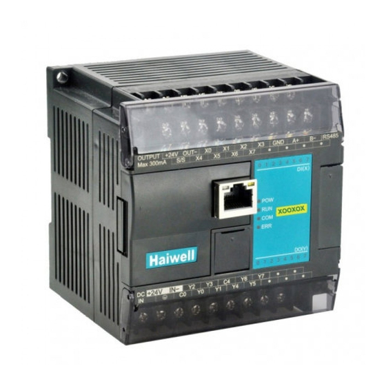
Haiwell S04XA User Manual & Application Case
Programmable logic controller
Hide thumbs
1
Table Of Contents
2
3
4
5
6
7
8
9
10
11
12
13
14
15
16
17
18
page
of
18
Go
/
18
Contents
Table of Contents
Bookmarks
Table of Contents
Table of Contents
Analog Module User Manual
Product Model List and Dimension
Indicator Description
Power Supply Specification
Environmental Specifications for Product
Analog Input (AI) Specification
Analog Output (AQ) Specification
Analog Input (AI) Wiring Diagram
Analog Output (AQ) Wiring Diagram
MPU Terminal Wiring Diagram
Module Parameter Table (CR Code Is Corresponding to the Modbus Register Address)
4-Channel Analog Module Parameter Table
Mounting and Installation
Analog Module Application Case
Expand Module through the Host PLC Parallel Port
Module Power Supply
The Analog Need't be Written any Conversion Program, Read the Analog Register Value Directly
Programming Skills
Display Analog Value on SCADA, HMI
When the Engineering Value Is Not Used, the Default Code Value Is 0 ~ 32000
Module CR Code Application Example: Read the Module Channel Disconnection Alarm
Module Used as Remote IO
Module Power Supply
Communication Port Introduction
Communication Protocols and Default Parameters
Module Parameter Configuration Method Introduction, When the Module Is Used as Remote IO
Parameter Configuration Example: the Module Is Configured by Programming Software Remote Module Tool
Hardware Connection
Software Operation Steps
Remote IO Application Example(RS485 Mode): the PLC Read the 4 Communication Temperature Values of S04AI Module
Remote IO Application Example (RS485 Mode): the PLC Writes the 8-Channel Output Values of S08AO Module
Remote IO Application Example(Ethernet Mode): PLC Read and Write each Channel Input and Output Values of S08XA-E16
Haiwell Cloud Configuration Communicates Directly with S08AI Module Example
Advertisement
Quick Links
1
Table of Contents
2
Analog Module User Manual
3
Analog Input (Ai) Specification
4
Analog Input (Ai) Wiring Diagram
Download this manual
Haiwell PLC User Manual
Programmable Logic Controller
Analog Module User Manual & Application Case
Xiamen Haiwell Technology Co., Ltd.
www.haiwell.com
Table of
Contents
Previous
Page
Next
Page
1
2
3
4
5
Advertisement
Table of Contents
Need help?
Do you have a question about the S04XA and is the answer not in the manual?
Ask a question
Questions and answers
Related Manuals for Haiwell S04XA
Controller haiwell S04AI User Manual & Application Case
Programmable logic controller (18 pages)
Controller haiwell S08AI User Manual & Application Case
Programmable logic controller (18 pages)
Controller haiwell S08AO User Manual & Application Case
Programmable logic controller (18 pages)
Controller Haiwell H04DT User Manual
Programmable logic controller (23 pages)
Controller Haiwell PLC User Manual
Programmable logic controller (13 pages)
Controller Haiwell H Series User Manual
Programmable logic controller (6 pages)
Controller Haiwell T Series User Manual
Programmable logic controller (6 pages)
Controller Haiwell PLC User Manual
Classic programmable logic controller (24 pages)
Summarization of Contents
Analog Module User Manual
Product Model List and Dimension
Lists Haiwell PLC analog module models with their physical dimensions.
Indicator Description
Explains the function and status of PWR and LINK indicators on the modules.
Power Supply Specification
Details DC and AC power supply voltage, frequency, and protection requirements.
Environmental Specifications for Product
Outlines operating temperature, humidity, vibration, and impact resistance for the modules.
Analog Input (AI) Specification
Specifies input ranges, resolution, impedance, and precision for analog input modules.
Analog Output (AQ) Specification
Specifies output ranges, resolution, load impedance, and precision for analog output modules.
Analog Input (AI) Wiring Diagram
Illustrates wiring for various analog input signal types (voltage and current).
Analog Output (AQ) Wiring Diagram
Provides wiring diagrams for connecting analog output signals to external devices.
MPU Terminal Wiring Diagram
Shows terminal connections for different Haiwell PLC analog modules.
Module Parameter Table
Maps CR codes to Modbus register addresses for analog module parameter configuration.
Mounting and installation
Guides on module mounting, rail installation, and expansion module wiring.
Analog Module Application Case
Expand module through the host PLC parallel port
Covers module expansion via parallel port, including power, direct value reading, programming, display, default values, and disconnection alarms.
Module used as remote IO
Details using modules as remote I/O via RS485/Ethernet, including power, communication, protocols, configuration, and application examples.
Table of Contents
Print
Rename the bookmark
Delete bookmark?
Delete from my manuals?
Login
Sign In
OR
Sign in with Facebook
Sign in with Google
Upload manual
Upload from disk
Upload from URL
Need help?
Do you have a question about the S04XA and is the answer not in the manual?
Questions and answers