Sign In
Upload
Download
Table of Contents
Contents
Add to my manuals
Delete from my manuals
Share
URL of this page:
HTML Link:
Bookmark this page
Add
Manual will be automatically added to "My Manuals"
Print this page
×
Bookmark added
×
Added to my manuals
Manuals
Brands
Quorum Manuals
Laboratory Equipment
Q150T E
Instruction manual
Quorum Q150T E Instruction Manual
Sample preparation system
Hide thumbs
1
2
Table Of Contents
3
4
5
6
7
8
9
10
11
12
13
14
15
16
17
18
19
20
21
22
23
24
25
26
27
28
29
30
31
32
33
34
35
36
37
38
39
40
41
42
43
44
45
46
47
48
49
50
51
52
53
54
55
56
57
58
59
60
61
62
63
64
65
66
67
68
69
70
71
72
73
74
75
76
77
78
79
80
81
82
83
84
85
86
87
88
89
90
91
92
page
of
92
Go
/
92
Contents
Table of Contents
Troubleshooting
Bookmarks
Table of Contents
Table of Contents
1 Introduction
General Description
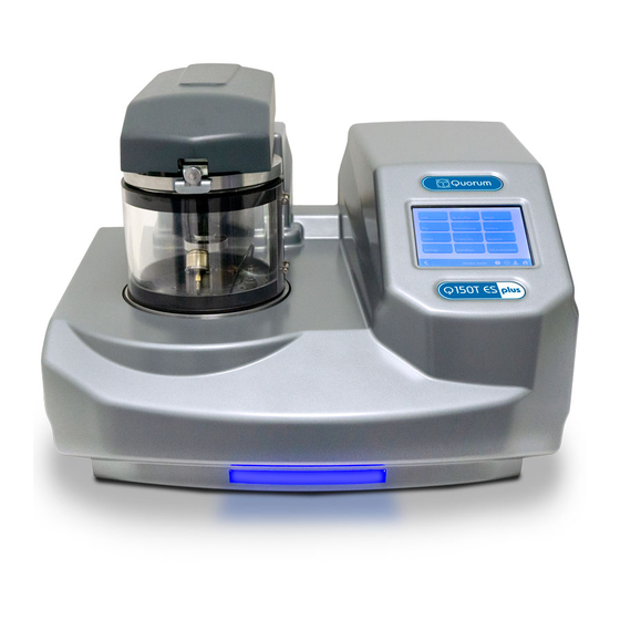
Figure 1-1. Front View of the Q150T
Sputter Coating
Carbon Coating
Metal Evaporation
Aperture Cleaning
2 Installation
Pre-Installation
Required Services
Unpacking
Connections
Figure 2-1. Q150T Rear Panel
Figure 2-2. Gas Connectors with Filter (Part No. 12842) Fitted to Purge Gas Inlet
Gas Connections
Aux Network Connection
Electrical Connections
Figure 2-3. Power Outlet Lead Wiring
Vacuum Connections
Figure 2-4. Fitting the Standard Stage
Fitting the Standard Stage
Optional Connections
3 Operation
Switching on for the First Time
The Standby Screen
Figure 3-1. Standby Screen
Running a Profile
Figure 3-2. Selecting a Profile
Table 1 Q150T Default Profiles
Figure 3-3. a Run in Progress: with FTM Installed (Left) and Without FTM (Right)
Figure 3-4. Venting the Chamber: with FTM Installed (Left) and Without FTM (Right)
System Settings
Figure 3-5. Listing System Properties for a Profile
Figure 3-6. Changing the Stage Rotate System Property
4 Working with Profiles
Editing the Active Profile
Profile Editor
Figure 4-1. Profile Editor
Table 2 Profile Icons
Creating a New Profile
Figure 4-2. Creating a New Profile
Figure 4-3. Entering a New Profile Name
Editing Profile Parameters
Figure 4-4. Editing Profile Parameters
Materials
Figure 4-5. Materials Editor
Table 3 Materials and Their Density
Creating a New Material
Editing Material Parameters
Table 4 Material Parameters
Deleting a Material
Figure 4-6. Material Parameters
5 Application Guidelines
QT Timed Sputter
Tungsten SEM Work
High Resolution SEM Coatings for Field Emission SEM
Aluminium Thin Film
QT FTM Terminated Sputter
High Resolution SEM Coatings for Field Emission SEM
General Thin Film Coatings
Metal Evaporation
How to Achieve a 20Nm Gold Coating
Figure 5-1. QT Metal Evaporation Process
Pulsed Cord Evaporation
How to Create a 20Nm Carbon Coating
5.5 Controlled Pulse Cord Evaporation
Using Controlled Pulse to Create a 15Nm Coat or 2-3Nm for EBSD
Table 5 QT Pulsed Cord Evaporation Parameters for 20Nm Coating
Table 6 QT Controlled Pulsed Cord Evaporation Parameters for 25Nm Coating
Figure 5-2. Typical 12Nm Controlled Pulse Evaporation
Pulsed Rod Evaporation
How to Create a Conductive Layer for SEM
Table 7 QT Pulsed Rod Evaporation Parameters for Conductive Layer for SEM
Ramped Profile
Carbon Insert Setup
Figure 5-3. Wedge Tool (Part No. 12097)
Figure 5-4. (L) a Finished Wedge-Shaped Rod; and (R) in Position with Plain Rod
The Ramped Current Profile
Figure 5-5. Ramped Profile with Default Parameters
Adjusting Coating Thickness
How to Create a Carbon Support Layer for TEM
Table 8 QT Ramped Carbon TEM Parameters for 5Nm Coating
How to Create a Conductive Carbon Layer for SEM
Table 9 QT Ramped Carbon Parameters for SEM Coatings
Using Outgas Source Options
Setting Outgas Source Options
Running Multiple Outgassing
Figure 5-6. Prompts to Repeat the Outgas Procedure (Left) and Proceed with Coating (Right)
Table 10 Outgas Source Options
Glow Discharge
Hydrophilisation
Surface Cleaning
Table 11 Glow Discharge Treatments
Aperture Cleaning
Figure 5-7. Aperture Cleaning in Progress
6 Instrument Management
The Q150T Menus
Table 12 Q150T Menus
Instrument Settings
Figure 6-1. System Editor
Figure 6-2. Network Properties
Figure 6-3. Active Ftp Address
Network
Figure 6-4. Generic Sputter Parameters
Generic Sputter
Table 13 Generic Sputter Parameters
Figure 6-5. Vacuum Parameters
Table 14 Vacuum Parameters
Vacuum
Figure 6-6. Maintenance Settings
Maintenance
Table 15 Maintenance Settings
Figure 6-7. Hardware Settings (Single Target)
Hardware
Table 16 Hardware Settings
User Management
Changing User Group
Figure 6-8. Changing the User Level
Managing User Groups
Figure 6-9. Managing User Groups
Film Thickness Monitor
Setting the Date and Time
Figure 6-10. FTM Status
Figure 6-11. Setting the Date and Time
Setting up a Network Connection
Configuring a Firewall Exception for Windows Explorer
Connecting the Q150
Figure 6-12. Connecting the Q150 to a Network
Network Troubleshooting
Process Logging
Figure 6-13. Process Log and Browse Buttons
Figure 6-14. Process Log Detail
7 Accessories
Sputter Insert
Figure 7-1. Top View of the Sputter Insert
Figure 7-2. Sputter Insert and Target Assembly
Carbon Rod Insert
Figure 7-3. Carbon Rod Insert
Figure 7-4. Recommended Carbon Rod Shapes
Figure 7-5. Carbon Rod Shaper (S8650/S8651))
Shaping Carbon Rods for Pulsed Evaporation
Shaping Carbon Rods for Ramped Evaporation
Fitting the Carbon Fibre Insert
Figure 7-6. Carbon String Insert
Metal Evaporation Insert
Installing a Wire Basket
Installing a Molybdenum Boat for Aperture Cleaning
Figure 7-7. Fitting the Metal Evaporation Insert for Downwards Evaporation
Adapting the Insert for Upwards Evaporation
Figure 7-8. Metal Evaporation Insert Adapted for Upwards Evaporation
Glow Discharge Insert
Figure 7-9. Glow Discharge Insert
Figure 7-10. Removing the Shutter
Rotacota Stage
Figure 7-11. Rotacota Stage
Slide Stage
Figure 7-12. Slide Stage
102Mm Stage and Gearbox
Figure 7-13. Large (102Mm) Sample Stage and Gearbox
Tilt Stage
Figure 7-14. Adjustable Tilting Stage
Film Thickness Monitor (FTM)
Replacing the FTM Crystal
Figure 7-15. FTM (Left); Replacing the FTM Crystal (Centre); FTM Lead (Right)
Extended Height Cylinder
Full Range Vacuum Gauge Assembly
Figure 7-16. the Extended Height Cylinder in Position
Rotating Vacuum Spigot
Figure 7-17. Rotating Vacuum Spigot
Emergency Stop Module
Figure 7-18. the Emergency Stop Module
Figure 7-19. Connecting the Emergency Stop Module
Spares
Table 17 Spare Parts for the Q150T
Table 18 Replacement Targets for Q150T S and Q150T es
Other Accessories
Table 19 Accessories for the Q150T
8 Service and Maintenance
Maintenance
Table 20 Maintenance Tasks
Troubleshooting
Error Messages
Table 21 Error Messages
Table 22 Warning Messages
Table 23 Information Messages
9 Appendices
Profile Parameters
Table 24 Ftm/Timed Sputter Coating Parameters
Table 25 Carbon Pulse/Rod Evaporation Profile Parameters
Table 26 Controlled Pulse Cord
Table 27 Ramped Profile Parameters
Table 28 Metal Evaporation Profile Parameters
System Overrideable Parameters
Table 29 Aperture Cleaning Profile Parameters
Table 30 Vacuum Shutdown Properties
Table 31 System Override Properties
Technical Specification
Table 32 Technical Specification
Sputtering Deposition Rate
Figure 9-1. Sputtering Deposition Rate Using Gold
Figure 9-2. Sputtering Deposition Rate Using Chromium
Figure 9-3. Sputtering Deposition Rate Using Silver
Return of Goods
General Introduction
Health and Safety Declaration
Despatch
Return Address
Declaration of Contamination Form
Table 33 Declaration of Contamination Form
10 Index
Advertisement
Quick Links
1
General Description
2
Sputter Coating
Download this manual
Q150T S/E/ES
Sample Preparation System
Instruction Manual
10473
Issue 5
For technical and applications advice plus our on-line shop for
spares and consumable parts visit
www.quorumtech.com
Table of
Contents
Previous
Page
Next
Page
1
2
3
4
5
Advertisement
Table of Contents
Troubleshooting
Network Troubleshooting
53
Troubleshooting
75
Need help?
Do you have a question about the Q150T E and is the answer not in the manual?
Ask a question
Questions and answers
Related Manuals for Quorum Q150T E
Laboratory Equipment Quorum Q150T S Instruction Manual
Sample preparation system (92 pages)
Laboratory Equipment Quorum Q150T ES Instruction Manual
Sample preparation system (92 pages)
Laboratory Equipment Quorum Q150T Fitting Instructions
Sputter insert (2 pages)
Laboratory Equipment Quorum SC7610 Operating Manual
Sputter coater (31 pages)
Table of Contents
Save PDF
Print
Rename the bookmark
Delete bookmark?
Delete from my manuals?
Login
Sign In
OR
Sign in with Facebook
Sign in with Google
Upload manual
Upload from disk
Upload from URL


Need help?
Do you have a question about the Q150T E and is the answer not in the manual?
Questions and answers