
Subscribe to Our Youtube Channel
Related Manuals for Quorum Q150T S

Summary of Contents for Quorum Q150T S
- Page 1 Q150T S/E/ES Sample Preparation System Instruction Manual 10473 Issue 5 For technical and applications advice plus our on-line shop for spares and consumable parts visit www.quorumtech.com...
- Page 2 No performance guarantees, however, can be given in circumstances where these component packages are used in conjunction with equipment supplied by companies other than Quorum Technologies Ltd. www.quorumtech.com Quorum Technologies Limited Company No. 04273003...
-
Page 3: Table Of Contents
Q150T Sample Preparation System Contents Section Contents Introduction ......................8 1.1 General Description ..................8 1.2 Sputter Coating ....................9 1.3 Carbon Coating....................9 1.4 Metal Evaporation .................... 9 1.5 Aperture Cleaning .................... 9 Installation ......................10 2.1 Pre-installation ....................10 2.1.1 Required Services .......................10 2.2 Unpacking...................... - Page 4 Q150T Sample Preparation System 5.10 Aperture Cleaning ..................41 Instrument Management ..................42 6.1 The Q150T Menus ..................42 6.2 Instrument Settings ..................43 6.2.1 Network ........................44 6.2.2 Generic Sputter......................45 6.2.3 Vacuum........................46 6.2.4 Maintenance........................47 6.2.5 Hardware........................48 6.3 User Management..................49 6.3.1 Changing User Group ....................49 6.3.2...
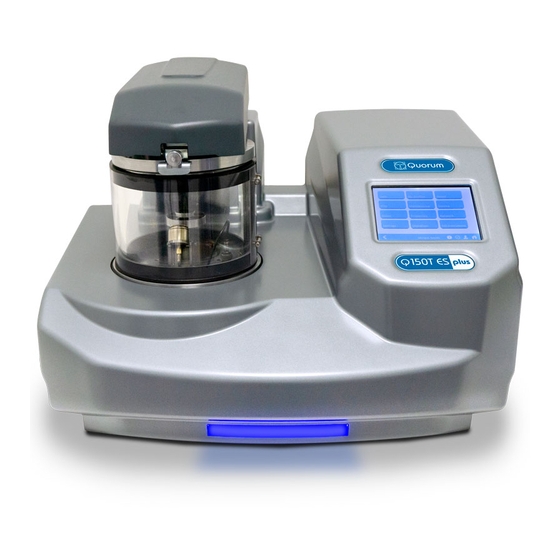
- Page 5 Q150T Sample Preparation System List of Figures Figure 1-1. Front view of the Q150T....................8 Figure 2-1. Q150T Rear Panel ......................12 Figure 2-2. Gas connectors with filter (part no. 12842) fitted to purge gas inlet ......13 Figure 2-3. Power outlet lead wiring....................14 Figure 2-4.
- Page 6 Maintenance settings ....................47 Table 16 Hardware settings .......................48 Table 17 Spare Parts for the Q150T..................72 Table 18 Replacement targets for Q150T S and Q150T ES .............72 Table 19 Accessories for the Q150T ..................73 Table 20 Maintenance Tasks .....................74 Table 21 Error Messages......................75...
- Page 7 All service work carried out on the equipment should only be undertaken by suitably qualified personnel. Quorum is not liable for any damage, injury or consequential loss resulting from servicing by unqualified personnel. Quorum will also not be liable for damage, injury or consequential loss resulting from incorrect operation of the instrument or modification of the instrument.
-
Page 8: Introduction
Evaporate metals upwards or downwards from a wire basket or molybdenum boat arrangement. Clean aperture strips. There are three models in the Q150T range: Q150T S Sputter coater version only. Q150T E Carbon/metal evaporation version only. Q150T ES Combined system with interchangeable inserts for sputter coating or carbon/metal evaporation. -
Page 9: Sputter Coating
'charging', reduce thermal damage, and enhance secondary electron emission. The Q150T S and Q150T ES employ a magnetron sputter target assembly. This enhances the efficiency of the process using low voltages and giving a fine-grain (order of 0.5nm Cr grain size), cool sputtering. -
Page 10: Installation
Q150T Sample Preparation System Installation It is important that this equipment is installed by skilled personnel in accordance with these instructions. Failure to do so may result in damage or injury. 'If in doubt - ASK'. Pre-installation Identify a suitable location for the unit: ... -
Page 11: Unpacking
Q150T Sample Preparation System Unpacking Remove the Instrument from its packing and place it in its operational position. CAUTION Don’t try to lift the unit by yourself: it weighs 33.4kg. Get someone to help you move it. Carry out a visual inspection to check for any signs of transit damage. Remove the Accessories Pack, and check contents against Q150T Accessories Pack shipping list. -
Page 12: Connections
Q150T Sample Preparation System Connections Installation consists of the following steps: Connect gas supplies (see below). Make electrical connections (see page 13). Connect the vacuum pump (see page 15). Install the sample stage (see page 16). If you want to install a different insert than that supplied with your instrument, please see page 54. -
Page 13: Gas Connections
Q150T Sample Preparation System 2.3.1 Gas Connections Connect a suitable argon supply at a regulated input of 0.3bar (4psi) to the quick connect Argon gas connector on the rear panel (see Figure 2-1. If you prefer, you can use argon for both process and purge supplies.(recommended if coating with oxidising targets). -
Page 14: Electrical Connections
Q150T Sample Preparation System 2.3.2 Electrical Connections Connect the instrument to a suitable earthed single-phase ac supply using the supplied cable. The lead should be fitted with the appropriate plug for your country. Ensure the plug is firmly located. WARNING – EARTH CONNECTION This Equipment must be Earthed and fitted with the correct lead for the country of operation. -
Page 15: Vacuum Connections
Q150T Sample Preparation System 2.3.4 Vacuum Connections If you are using an existing or alternative vacuum pump, and have any difficulty with connections, please ask for advice. If the instrument is NOT going to be vented into an extraction system, fit an Oil Mist Filter with metal adapter to the outlet of the vacuum pump. -
Page 16: Fitting The Standard Stage
Q150T Sample Preparation System 2.3.5 Fitting the Standard Stage The Q150T is supplied with a standard stage (10067). For installation instructions for other stages, see page 54. To install the standard stage: Ensure that the instrument is vented and in standby mode. Open the top cover fully so it rests against its backstop. -
Page 17: Operation
Q150T Sample Preparation System Operation This chapter describes the basic operation of the Q150T. For more advanced use, please see Working with Profiles on page 21 and Application Guidelines on page 28. Switching On for the First Time Ensure that you have completed the installation as described in the previous sections. -
Page 18: Running A Profile
Q150T Sample Preparation System Running a Profile Before you can run a profile, ensure you have: Completed the installation as described on page 10. Switched on the instrument (see section 17). Loaded a sputter/coating target or loaded an evaporation source (see page 54). ... -
Page 19: Figure 3-3. A Run In Progress: With Ftm Installed (Left) And Without Ftm (Right)
Q150T Sample Preparation System Figure 3-3. A run in progress: with FTM installed (left) and without FTM (right). If you want to stop a run while it is in progress, tap on the Cancel button. At the completion of the run, the Q150T begins to vent the chamber (see Figure 3-4). -
Page 20: System Settings
Q150T Sample Preparation System System Settings The operation of the Q150T is controlled by its profile parameters. However, there are several system parameters, which can be changed without altering the profile. A system- set parameter overrides the corresponding setting specified in the active profile. You can make the new setting apply just to runs using the active profile or to all runs, irrespective of the choice of profile. -
Page 21: Working With Profiles
Q150T Sample Preparation System Working with Profiles The operation of the Q150T is controlled by a profile. This describes the sequence of operations in sputter coating or evaporation cycles. You can also create profiles to carry out simple operations such as pumping or venting the sample chamber. Many of the basic operations such as pumping, outgassing or venting the chamber occur automatically as does the sequence in which they occur. -
Page 22: Table 2 Profile Icons
Q150T Sample Preparation System In its main window, Profile Editor lists all existing profiles. To the left of each profile name, an icon denotes the type of profile (see Table 2). Table 2 Profile icons Icon Profile/Process Type Timed sputter (see Table 24) FTM terminated sputter (see Table 24) Aperture cleaning (see Table 29) Metal evaporation (see Table 28) -
Page 23: Creating A New Profile
See Table 2 for a list of all the available processes. Note that the processes listed are different for Q150T E, Q150T S and Q150T ES models. Enter a name for the profile: tap in the Name field to display the on-screen keyboard (Figure 4-3) in the Enter Name dialog box. -
Page 24: Editing Profile Parameters
Q150T Sample Preparation System 4.2.2 Editing Profile Parameters To edit a profile, tap on its name in Profile Editor and then tap on the Edit button. A table showing the profile’s parameters is displayed. To edit a parameter, tap on its value (it is then highlighted in blue) and then tap on the Edit button. -
Page 25: Materials
Q150T Sample Preparation System Materials The software contains a database of the most common elements and alloys used in sputtering and evaporation applications (see Table 3). The choice of material is the first parameter in a Sputter Coating profile. The embedded density information is used to calculate film thickness. -
Page 26: Creating A New Material
Only used during pulse cleaning of target. * Displayed for information only. Changes if required will need to be carried out by a Quorum agent. 10473 - Issue 5 Q150T - Instruction Manual... -
Page 27: Deleting A Material
Q150T Sample Preparation System To edit a material: Tap on the material’s name and then tap on the Edit button. To edit a parameter, tap on its value (it is then highlighted in blue) and then tap on the Edit button. Change the value as required. -
Page 28: Application Guidelines
Q150T Sample Preparation System Application Guidelines This section describes the QT processes and their typical applications. QT Timed Sputter Suitable for the following applications: SEM coatings for tungsten emission SEM. High resolution SEM coatings for field emission SEM. General thin film coatings. -
Page 29: Aluminium Thin Film
Q150T Sample Preparation System 5.1.3 Aluminium thin film Aluminium is often difficult to coat due to its fast oxidizing properties. Also, its oxidized layer is difficult to remove as it reduces the required target voltage to produce a sputter current of 150mA. This increases the time required to clean the target. However, the Q150T is set up to cycle the plasma which reduces this cleaning time. -
Page 30: Qt Ftm Terminated Sputter
Q150T Sample Preparation System QT FTM Terminated Sputter This process (only available if the FTM is fitted) is suited to the following typical applications: SEM coatings for tungsten emission SEM. High resolution SEM coatings for field emission FE- SEM. General thin film coatings. -
Page 31: Metal Evaporation
Q150T Sample Preparation System Metal Evaporation This process is designed for the following applications: Alternative coatings methods for SEM samples where sputtering is not available. Coating metal films on Non EM substrates. It is only available with Q150T E/ES models equipped with the optional metal evaporation insert. -
Page 32: Pulsed Cord Evaporation
Q150T Sample Preparation System Pulsed Cord Evaporation This process is designed for preparing conductive carbon coatings for SEM specimens for X-ray microanalysis EDX and WDX. It is only available with Q150T E/ES models equipped with the carbon cord insert option. 5.4.1 How to create a 20nm carbon coating Install the carbon cord insert as described on page 58. -
Page 33: Figure 5-2. Typical 12Nm Controlled Pulse Evaporation
Q150T Sample Preparation System order to reduce this error the system attempts to detect when the cord is about to fuse. If detected the coater will assume next pulse will produce 6 nm thus will apply the pulse if the predicted outcome would be closer to the terminate value. For a full list of profile parameters see Table 26. -
Page 34: Pulsed Rod Evaporation
Q150T Sample Preparation System Pulsed Rod Evaporation Use this process for preparing TEM coatings for applying carbon reinforcement layers onto formvar grids. It is only available with Q150T E/ES models. 5.6.1 How to create a conductive layer for SEM Install the carbon insert as described on page 54. Ensure that the carbon rods are prepared with a 1.2mm diameter spigot correctly as described on page 56. -
Page 35: Ramped Profile
Q150T Sample Preparation System Ramped Profile The Q150T Ramped Profile produces carbon coatings from a shaped carbon rod. We recommend this profile instead of the pulse carbon rod process if you require a consistently repeatable deposited thickness. Generally, this process requires the use of the extended height chamber (see page 69). The short chamber may be used for a coating thickness greater than 12nm although the FTM will be inaccurate due to the close proximity of the high temperate rods. -
Page 36: The Ramped Current Profile
Q150T Sample Preparation System 5.7.2 The ramped current profile To achieve the controlled thickness this process uses a controlled evaporation current profile (see Figure 5-5). Ramped carbon process Current increasing at Current Ramp Rate Ramp terminated at Evaporation Current Ramp terminated PreEvap End current Outgas current... -
Page 37: Adjusting Coating Thickness
Q150T Sample Preparation System 5.7.3 Adjusting coating thickness The default settings in the Ramped Profile will produce a 15 to 20nm coating suitable for SEM use. The actual coating thickness will depend on the stage height and the diameter of the spigot produced by your sharpener. As an approximate guide, the coating thickness is proportional to the square of the distance between the stage height and the rods (the same amount of material is distributed over an increasing area as it travels away from the rods). -
Page 38: How To Create A Conductive Carbon Layer For Sem
Q150T Sample Preparation System How to create a conductive carbon layer for SEM Install the carbon insert as described on page 56. Ensure that the carbon rods are prepared correctly as described on page 57. Ensure the stage is fitted with the longer support shaft adjusted to a height of 75mm above the base plate. -
Page 39: Using Outgas Source Options
Q150T Sample Preparation System Using Outgas Source options In addition to the evaporation parameters described in the previous section, you can also set up enhanced outgassing with the Outgas Source user parameter. This has three settings: multiple, single or none as described in Table 10. You need to be logged in at Administrator level to access this parameter (see page 49). -
Page 40: Glow Discharge
Glow Discharge This process can be used to clean hydrocarbon contamination from components. It is only available with Q150T S and ES models which are equipped with the Sputter power supply Carefully fit the insert as described on page 62. -
Page 41: Aperture Cleaning
Q150T Sample Preparation System 5.10 Aperture Cleaning This process is designed to clean hydrocarbon contamination from SEM & TEM apertures. It is only available with Q150T E/ES models equipped with the optional metal evaporation insert. Fit the molybdenum boat source to the evaporation insert as described on page 59 Choose the QT aperture cleaning profile from the list. -
Page 42: Instrument Management
Q150T Sample Preparation System Instrument Management The software controls the general operation of the instrument through a system of default settings. This section describes how you can: Change general instrument settings Define the Network address and set up a connection ... -
Page 43: Instrument Settings
Q150T Sample Preparation System Instrument Settings The specific operation of the Q150T is determined by the settings of the active profile. Default sputter settings and general hardware settings are configured through System Editor. To view the System Editor, select Edit | System from the menu bar (see Figure 6-1). Figure 6-1. -
Page 44: Network
Q150T Sample Preparation System 6.2.1 Network The Network category determines the IP address used by the instrument for Network connections. To edit network properties, tap on Network and then tap on the Edit button. The Network Properties are displayed (see Figure 6-2). Figure 6-2. -
Page 45: Generic Sputter
Q150T Sample Preparation System 6.2.2 Generic Sputter This option allows you to change the default settings used during sputter coating sequences. The Q150T uses these settings in all profiles of type: Timed Sputter and FTM Terminated Sputter unless overridden in the profile (see page 83). To change the settings, tap on Generic Sputter and then tap on the Edit button. -
Page 46: Vacuum
Q150T Sample Preparation System 6.2.3 Vacuum This option allows you to change the default settings for pumping/venting cycles used in both sputter coating and evaporation sequences. The Q150T uses these settings in all profiles. To change the settings, tap on Vacuum and then tap on the Edit button. The Vacuum properties are displayed (see Figure 6-5 and Table 14). -
Page 47: Maintenance
Q150T Sample Preparation System When you edit a value, click on the OK button to confirm the change or on the Cancel button to restore the previous value. Edit other parameters as required. Back on the Vacuum page, click on the OK button to confirm the changes or on the Cancel button to restore the previous values. -
Page 48: Hardware
Q150T Sample Preparation System Edit other parameters as required. Back on the Maintenance page, click on the OK button to confirm the changes or on the Cancel button to restore the previous values. 6.2.5 Hardware This option allows you to change the settings defining the configuration of your instrument. -
Page 49: User Management
Q150T Sample Preparation System When you edit a value, click on the OK button to confirm the change or on the Cancel button to restore the previous value. Edit other parameters as required. Back on the Hardware page, click on the OK button to confirm the changes or on the Cancel button to restore the previous values. -
Page 50: Managing User Groups
Q150T Sample Preparation System 6.3.2 Managing User Groups The Q150T software is set up with User and Administration access levels. There is also the facility for creating new user groups with customised access privileges or for editing or deleting existing groups. To manage user groups, select Edit | User | Groups from the menu bar. -
Page 51: Film Thickness Monitor
Q150T Sample Preparation System Film Thickness Monitor To view the status of the Film Thickness Monitor (FTM), select Service | FTM from the menu bar. The FTM Status window is displayed (see Figure 6-10). This shows the percentage of the crystal used and will help you decide when to replace it (see page 68). -
Page 52: Setting Up A Network Connection
Windows Explorer displays a list of files stored on the Q150. You can copy files to or from the instrument. Only files supplied by Quorum or previously copied or moved from the instrument should be transferred. A file cannot be opened directly from the instrument;... -
Page 53: Network Troubleshooting
Q150T Sample Preparation System 6.6.3 Network Troubleshooting If the connection fails, check that the first three numbers in the IP addresses of the instrument and the computer are the same. Check the firewall settings. The Q150 will only support one connection. For example, it will not allow simultaneous connections to Internet Explorer and Windows Explorer. -
Page 54: Accessories
The QT150T can be configured for various sputtering and evaporation applications. This section describes the installation of: Sputter insert pre-installed as standard on Q150T S and Q150T ES models. Includes instructions for changing the target. Additional sputter insert available (10453). -
Page 55: Figure 7-2. Sputter Insert And Target Assembly
Q150T Sample Preparation System Turn the two securing buttons to release the installed insert and remove the insert (see Figure 7-1). Q150T ES users only: If the insert is a carbon rod type you may have to remove the rods first (see page 56). To do this, check that the securing buttons are restraining the insert and open the lid assembly and rest it against the top cover assembly. -
Page 56: Carbon Rod Insert
Q150T Sample Preparation System Carbon Rod Insert This section describes the installation of the carbon rod insert supplied with Q150T E and Q150T ES instruments. There are two inserts designed to accommodate 3mm carbon rods (10033) or 6mm rods (10456). To install the carbon rod insert: Check the machine is not operating. -
Page 57: Shaping Carbon Rods For Pulsed Evaporation
Carbon Rod Shaper (S8650/S8651)) To shape a carbon rod: Cut a 50mm length of rod. Use only Quorum rods due to the varying diameter and quality of other manufacturer’s rods. Quorum supply rods in two sizes: 3mm (C5422) and 6mm (C5423). -
Page 58: Shaping Carbon Rods For Ramped Evaporation
Q150T Sample Preparation System If the rod tip should break in the cutter, it can be removed by unscrewing the brass coupling, removing the cutter and pushing out the broken rod tip, while avoid damaging the teeth of the cutter. WARNING TAKE CARE WHEN HANDLING THE CUTTER: IT IS VERY SHARP. -
Page 59: Metal Evaporation Insert
Q150T Sample Preparation System Metal Evaporation Insert This section describes the installation of the metal evaporation insert (10457) designed for downwards evaporation (see Figure 7-7). To install the stage: Check the machine is not operating. Press down firmly on the top cover to release the latch. (See note below.). Lift the top cover and rest it against its stop. -
Page 60: Adapting The Insert For Upwards Evaporation
Q150T Sample Preparation System Check the copper terminal contacts on the top of the insert are clean and free from damage (they must have a flat top face.) and that the contacts in the underside of the top cover assembly are also clean and flat. Close the top cover assembly and press firmly down to secure the latch. -
Page 61: Figure 7-8. Metal Evaporation Insert Adapted For Upwards Evaporation
Q150T Sample Preparation System Outer ring O-ring Sample holder Electrode extension Wire basket Figure 7-8. Metal evaporation insert adapted for upwards evaporation Q150T - Instruction Manual 10473 - Issue 5... -
Page 62: Glow Discharge Insert
Q150T Sample Preparation System Glow Discharge Insert This section describes the installation of the glow discharge insert (Part No. 10837). WARNING – HIGH VOLTAGES AND HIGH VACUUM This equipment produces high voltages and high vacuum in its operation. Figure 7-9. Glow discharge insert Check the machine is not operating. -
Page 63: Figure 7-10. Removing The Shutter
Q150T Sample Preparation System Figure 7-10. Removing the shutter To ensure the correct operation of the glow discharge accessory install the restrictor plate (see below). Q150T - Instruction Manual 10473 - Issue 5... -
Page 64: Rotacota Stage
Q150T Sample Preparation System Rotacota Stage The Rotacota stage (10360) is an offset rotating stage, with tilting sample holder, designed to improve the even distribution of sputtering or evaporation (see Figure 7-11). Check the machine is not operating. Open the top cover fully so it rests against its backstop. Remove any installed sample stage by lifting carefully upwards. -
Page 65: Slide Stage
Q150T Sample Preparation System Slide Stage To install the slide sample stage (10358): Check the machine is not operating. Open the top cover fully so it rests against its backstop. Remove any installed stage by lifting carefully upwards. Slide sample stage Height-adjusting collar Stage shaft Rotation drive... -
Page 66: 102Mm Stage And Gearbox
Q150T Sample Preparation System 102mm Stage and Gearbox The 102mm stage (10458) is designed to hold 102mm (4”) silicon wafers (see Figure 7-13). If you want to use a FTM with this stage, install the stage gearbox assembly (10359). The sample stage gearbox allows you to install the sample stage in an offset rotating position. -
Page 67: Tilt Stage
Q150T Sample Preparation System Tilt Stage The tilt stage (10357) allows you to vary the sample angle or height (see Figure 7-14). To fit the tilt stage: Check the machine is not operating. Open the top cover fully so that it rests against its back stop. Remove any installed stage by lifting carefully upwards. -
Page 68: Film Thickness Monitor (Ftm)
Q150T Sample Preparation System 7.10 Film Thickness Monitor (FTM) If you have specified an FTM on the configuration of your Q150T it will be preinstalled. To install the film thickness monitor (10362): Check the machine is not operating. Open the top cover fully so it rests against its backstop. Remove the glass chamber assembly. -
Page 69: Extended Height Cylinder
Full Range Vacuum Gauge Assembly option (10428) extends the accurate measurement range to 1000 – 5x10 mbar. Contact Quorum for further information. Q150T - Instruction Manual 10473 - Issue 5... -
Page 70: Rotating Vacuum Spigot
Q150T Sample Preparation System 7.13 Rotating Vacuum Spigot The vacuum spigot (10422) allows more convenient connection of a vacuum hose to the rear of the Q150T when the instrument is located close to a wall, bench upstand or other obstruction (see Figure 7-17). Figure 7-17. -
Page 71: Emergency Stop Module
Q150T Sample Preparation System 7.14 Emergency Stop Module The emergency stop module (Part No. 11223) sits on top of the right hand side of the instrument. In the assembly there is the main stop box, the power plug and cable and the safety bracket to stop removal of the power plug. -
Page 72: Spares
Q150T Sample Preparation System 7.15 Spares The following are available from Quorum, or your local distributor, and are featured in more detail on the Quorum website: www.quorumtech.com. Table 17 Spare Parts for the Q150T SPARES FOR Q150T CATALOGUE QUANTITY NUMBER Carbon rods 3.05mm... -
Page 73: Other Accessories
TK8906 57mm Dia x 0.3mm ITO Target TK8907 * Requires spacer A4117193 under shield (see page 54 and Figure 7-2). Quorum can supply a wider range of target materials and thickness’. Please enquire for details. 7.16 Other Accessories The following are available from Quorum or your local distributor. -
Page 74: Service And Maintenance
Check oil mist filter for saturation. This is a disposable plastic filter regularly as and cannot be reactivated. required. Obtain consumable items from Quorum or an approved distributor only. Use only Quorum recommended items. For technical assistance and advice - contact Quorum. -
Page 75: Troubleshooting
Q150T Sample Preparation System Troubleshooting Routine service should not be necessary. In the event of non-operation, carry out the following checks. CAUTION Disconnect the power cord BEFORE carrying out any servicing activities. Check power to Instrument. Check fuse. Check vacuum pump local switch should be in 'on' position. - Page 76 Q150T Sample Preparation System Error messages Description of fault shorts between the source terminals and the insert base. Process stopped due to FTM The FTM has stopped oscillating during the coating. crystal failure Interlock has been activated This is most likely caused by the top cover being opened during a cycle process stopped Unable to strike plasma...
-
Page 77: Table 22 Warning Messages
Q150T Sample Preparation System Table 22 Warning Messages Warning messages Description The top cover above the chamber has not been closed on Please close top cover. to the chamber lid Press OK when done The sputter head needs to be fitted Please fit sputter head and close the Top cover. -
Page 78: Appendices
Q150T Sample Preparation System Appendices Profile Parameters Operation of the Q150T is controlled by a process profile. There are several types of profile as listed in Table 24. Each profile contains a number of adjustable parameters. The following tables list the parameters available in each type of profile, showing their default values and allowed ranges. -
Page 79: Table 25 Carbon Pulse/Rod Evaporation Profile Parameters
Q150T Sample Preparation System Table 25 Carbon Pulse/Rod Evaporation profile parameters Name Default Minimum Maximum Comment Value Value Value Material Carbon Fixed; read only parameter Pulse current (A) 60 (cord) Current applied to cord during 75 (rod) the evaporation pulse Max Pulse 20 (cord) The voltage across the cord is... -
Page 80: Table 26 Controlled Pulse Cord
Q150T Sample Preparation System Table 26 Controlled Pulse cord Name Default Minimum Maximum Comment Value Value Value Terminate Terminate the coating when the thickness FTM measured thickness reaches this value Pulse Resolution Requested deposition on FTM for each pulse. Note this should be multiplied by the tooling factor to find the expected stage thickness for each pulse. -
Page 81: Table 27 Ramped Profile Parameters
Q150T Sample Preparation System Table 27 Ramped profile parameters Name Default Minimum Maximum Comment Value Value Value Evaporation Maximum evaporation current. Current Evaporation time The time the current is applied. (min) Starts when the evaporation Current exceeds Pre Evap end current. -
Page 82: Table 28 Metal Evaporation Profile Parameters
Q150T Sample Preparation System Table 28 Metal Evaporation profile parameters Name Default Minimum Maximum Comment Value Value Value Material Carbon Material to be evaporated in this process Evaporation Current applied during the Current (A) evaporation pulse Evaporation time Duration of evaporation pulse (Minutes) Out Gas Time Time source is outgassed... -
Page 83: System Overrideable Parameters
Q150T Sample Preparation System Table 29 Aperture Cleaning profile parameters Name Default Minimum Maximum Comment Value Value Value Evaporation 50** Current applied to evaporation Current (A) source during the evaporation. **If Max Evaporation Voltage parameter set below 2V the maximum value will increase to 100A. -
Page 84: Technical Specification
1000 - 5x10 mbar Fuse T 10A ceramic (5x20mm); fuse standard IEC60127-2 Weight 33.4 kg Sputter Coater (Q150T S and Q150T ES) Target 54mm Dia x 0.2mm Thick (Chromium fitted as Standard) Specimen Stage 60mm Dia. Rotating Stage Deposition Current... -
Page 85: Sputtering Deposition Rate
Q150T Sample Preparation System Sputtering Deposition Rate These graphs are provided for guidance only and are not to be taken for absolute reference 90.0 7*10-3 80.0 1*10-2 70.0 60.0 50.0 40.0 30.0 20.0 10.0 Deposition Current (mA) Figure 9-1. Sputtering Deposition Rate using Gold Gold tooling factor = 2.7 Q150T - Instruction Manual 10473 - Issue 5... -
Page 86: Figure 9-2. Sputtering Deposition Rate Using Chromium
Q150T Sample Preparation System 40.0 7*10-3 35.0 1*10-2 30.0 25.0 20.0 15.0 10.0 Depo sition Curren t (mA) Figure 9-2. Sputtering Deposition Rate using Chromium Chromium tooling factor = 2.28 10473 - Issue 5 Q150T - Instruction Manual... -
Page 87: Figure 9-3. Sputtering Deposition Rate Using Silver
Q150T Sample Preparation System 200.0 180.0 7*10-3 1*10-2 160.0 140.0 120.0 100.0 80.0 60.0 40.0 20.0 Deposition Current (mA) Figure 9-3. Sputtering Deposition Rate using Silver Silver tooling factor = 2.5 Q150T - Instruction Manual 10473 - Issue 5... -
Page 88: Return Of Goods
Seal in heavy duty polythene or a bag, Despatch in suitable transport container. 9.5.4 Return Address: F.A.O.: The Service Manager, Quorum Technologies, Units 1 & 2 Eden Business Centre South Stour Avenue, ASHFORD, Kent. TN23 7RS 10473 - Issue 5... -
Page 89: Declaration Of Contamination Form
Q150T Sample Preparation System 9.5.5 Declaration of Contamination Form Table 33 Declaration of Contamination Form Declaration of Contamination of Preparation Equipment and Accessories. The repair and/or service of Preparation Equipment and Accessories can only be carried out if a correctly completed declaration has been submitted. -
Page 90: Index
Q150T Sample Preparation System Index access code ..........49 Fail Safe ............7 accessories ..........73 film thickness monitor ......... 51 accessories ...........11, 54 filter ............13 emergency stop module......... 71 front view............8 rotating vacuum spigot ........70 administration..........49 installing............68 aluminium thin film ........29 relocating for upwards evaporation ....60 aperture cleaning...........9 replacing the crystal ........68... - Page 91 Q150T Sample Preparation System Set Date Time dialog box ......51 shaping carbon rods........57 Operation ............17 spares............72 outgas source..........39 specification..........84 outgassing...........39 sputter coating ..........9 overriding system settings ......83 sputtering............ 10 sputtering deposition rate......85 pre-installation..........10 stage rotate setting ........20 process log..........53 stages............
Need help?
Do you have a question about the Q150T S and is the answer not in the manual?
Questions and answers