Table of Contents
Advertisement
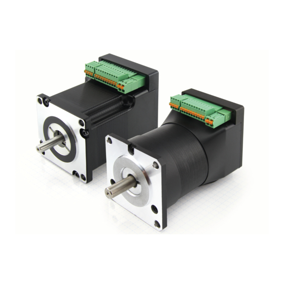
Manual PD4-C
Fieldbus: USB
For use with the following devices:
· PD4-C5918M4204-E-01
· PD4-C5918L4204-E-01
· PD4-C6018L4204-E-01
· PD4-CB59M024035-E-01
Valid with firmware version FIR-v1626
and since hardware version W005
NANOTEC ELECTRONIC GmbH & Co. KG
Kapellenstraße 6
85622 Feldkirchen/Munich, Germany
Manual Version: 1.4.1
Tel. +49 (0)89-900 686-0
Fax +49 (0)89 900 686-50
info@nanotec.com
Advertisement
Table of Contents

Related Manuals for NANOTEC PD4-C5918L4204-E-01


Summarization of Contents
Release Notes and Version History
Version Updates and Changes
Details on manual and firmware version updates and their associated changes.
Safety Instructions and Warnings
Important Safety Information and Manual Guidance
Essential technical manual reading guidance before installation and commissioning.
Personnel Qualifications for Safe Operation
Specifies requirements for skilled workers handling the motor controller safely.
General Danger and Warning Notes
Highlights general precautions and potential hazards when using the controller.
Understanding Danger and Warning Signs
Explains the standardized symbols used for hazard categorization in documentation.
Technical Data and Pin Configuration
Dimensioned Drawings of Motor Models
Provides detailed mechanical dimensions for different PD4-C and PD4-CB models.
Electrical Properties and Ratings
Details electrical properties, I/O specs, and motor ratings for different models.
Overtemperature Protection Mechanism
Explains how overtemperature is detected and handled by the controller.
LED Signaling for Status and Errors
Describes the meaning of the green operating LED and error indication patterns.
Pin Configuration Details
Details connector pin assignments for analogue input, clock/direction, and voltage supply.
Controller Configuration Options
General Configuration Methods Overview
Outlines options for configuring the motor controller: DIP switches, config file, NanoJ.
DIP Switch Settings for Mode Configuration
Describes how DIP switches on the rear configure operational modes and settings.
USB Port Usage and File Management
Explains the use of the USB port for connection, file storage, and firmware updates.
Configuration File Usage and Syntax
Details the purpose, syntax, and use of the configuration file for startup settings.
NanoJ Program Loading and Execution
Provides steps for loading and launching a NanoJ program on the motor controller.
Setup and Commissioning Guide
Safety Instructions for Setup and Commissioning
Critical safety warnings related to motor operation, maintenance, and wiring.
General Setup and Commissioning Procedures
Lists required components and general steps before setting up and commissioning.
General Concepts and Operating Principles
CANopen DS402 Power State Machine
Explains the state machine for switching the motor controller to an operational state.
User-Defined Units for Parameter Configuration
Describes how to set and use custom units for parameters like degrees or millimeters.
Operating Modes and Functions
Profile Position Mode Operation
Details the Profile Position Mode for relative or absolute target movements.
Velocity Operation Modes
Explains operation similar to a frequency converter, focusing on speed control.
Profile Velocity Mode Operation
Describes velocity mode with expanded ramps and external encoder speed monitoring.
Profile Torque Mode Operation
Details operation where torque is specified as the set point via a ramp function.
Homing Mode Functionality
Explains the purpose of reference runs for synchronizing the motor controller and encoder.
Clock/Direction Mode Operation
Describes operation using clock and direction input pins for target control.
Analogue Mode Operation
Explains operation using analogue input voltage height as the target.
Need help?
Do you have a question about the PD4-C5918L4204-E-01 and is the answer not in the manual?
Questions and answers