
Subscribe to Our Youtube Channel
Related Manuals for NANOTEC SMCI36


Summary of Contents for NANOTEC SMCI36
- Page 1 Technical Manual Controller for stepper and BLDC motors SMCI36 NANOTEC ELECTRONIC GmbH & Co. KG Tel. +49 (0)89-900 686-0 Gewerbestraße 11 +49 (0)89-900 686-50 D-85652 Landsham near Munich, Germany info@nanotec.de...
- Page 2 Technical Manual SMCI36 Editorial Editorial © 2011 ® Nanotec Electronic GmbH & Co. KG Gewerbestraße 11 D-85652 Landsham / Pliening Tel.: +49 (0)89-900 686-0 Fax: +49 (0)89-900 686-50 Internet: www.nanotec.de All rights reserved! MS-Windows 2000/XP/Vista/7 are registered trademarks of the Microsoft Corporation.
- Page 3 This technical manual must be carefully read before installing and commissioning the controller. ® In the interests of its customers and to improve the function of this product, Nanotec reserves the right to make technical alterations and further develop hardware and software without prior notice.
-
Page 4: Table Of Contents
Technical Manual SMCI36 Contents Contents Overview ..........................5 Connecting and commissioning ..................7 Overview ..........................7 Stepper motor ........................8 BLDC motor ........................... 9 Commissioning........................10 Connections and wiring ....................13 Hall sensor: Connector X1 ....................13 Inputs and outputs: Connectors X4 and X5 ................. 13 Encoder connection: Connector X2 .................. -
Page 5: Overview
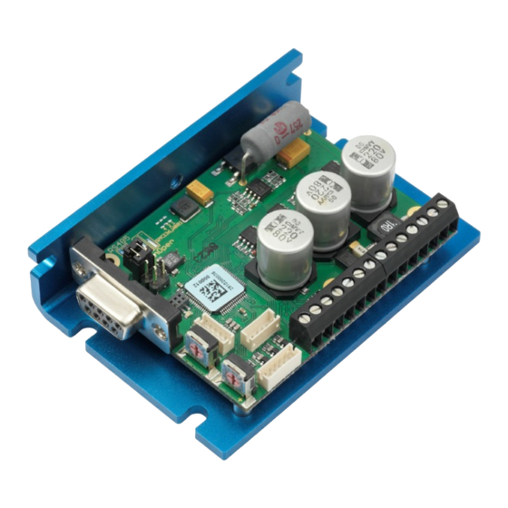
It is used for controlling standard stepper motors (including with attached encoders) or motors with an integrated encoder. BLDC motors are also supported. The SMCI36 is ideal for device installation due to its open, economical design and TTL signal level (5 V). For machine integration, we recommend the closed controllers SMCI33 and SMCI47-S-2, which can also process 24 V signals and are built on the same software basis. - Page 6 NanoCAN user manual. Presettings When the SMCI36 is delivered, it is preconfigured to relative positioning mode. The step mode can only be changed via software. It is preset to the half step setting. Due to microstep emulation, however, the stepper motor runs very smoothly and with excellent performance even in the half step.
-
Page 7: Connecting And Commissioning
Technical Manual SMCI36 Connecting and commissioning Connecting and commissioning Overview Connectors The controller has the following connectors: X1: Hall sensor X2: Encoder X3: Motor and power supply X4 and X5: Inputs and outputs X14: Communication (RS485/CAN) Jumper RS485/CAN The controller has a jumper field (X11/X12) for selecting the communication port (RS485 or CAN). -
Page 8: Stepper Motor
Connecting and commissioning Stepper motor Connection diagram To operate a stepper motor using the SMCI36, the wiring must be implemented according to the following connection diagram. The pin configuration for the motor can be found on the motor data sheet, which can be downloaded from www.nanotec.de. -
Page 9: Bldc Motor
Connecting and commissioning BLDC motor Connection diagram To operate a BLDC motor using the SMCI36, the wiring must be implemented according to the following connection diagram. The pin configuration for the motor can be found on the motor data sheet, which can be downloaded from www.nanotec.de. -
Page 10: Commissioning
This section describes the main first steps you need to take to be able to begin working with the SMCI36 and the NanoPro software (RS485) or NanoCAN software (CANopen) from a PC. You will find more detailed information in the separate NanoPro and NanoCAN manuals. - Page 11 Select the <Communication> tab. In the "Port" field, select the COM port to which The number of the COM the SMCI36 is connected. port to which the controller is connected can be found in the device manager of your Windows PC (System Control/System/Hardware).
- Page 12 Technical Manual SMCI36 Connecting and commissioning Commissioning with NanoCAN Proceed as follows when commissioning the controller with NanoCAN: Step Action Note Install the NanoCAN control software on your Download from www.nanotec.de Connect the controller to the stepper motor Connection diagram, see according to the connection diagram.
-
Page 13: Connections And Wiring
Technical Manual SMCI36 Connections and wiring Connections and wiring Hall sensor: Connector X1 Pin assignment Pin- Name Remark Hall 1 Hall 2 Hall 3 +5 V Inputs and outputs: Connectors X4 and X5 Introduction An overview of the assignments can be found in the connection diagram in Section 2. - Page 14 Technical Manual SMCI36 Connections and wiring Function of the inputs All digital inputs – with the exception of the "Clock" input in the clock directional mode – can be freely programmed using the NanoPro software (e.g. as a limit position switch, enable, etc.) and can be used for sequential control with NanoJ.
-
Page 15: Encoder Connection: Connector X2
The differential signal can be evaluated with a line driver/encoder adapter. Since the SMCI36 is designed for device installation, the differential signals are not evaluated so that only channels A, B and I need to be connected to perform position monitoring. -
Page 16: Motor And Power Supply Connection: Connector X3
3.4.2 Stepper motor connection General information The motor is connected to the SMCI36 with a 4-wire cable. Twisted wire pair cables with braided shields are recommended. Danger of electrical overvoltage Accidentally swapping the connections will destroy the output stage. See the data sheet of the connected stepper motor. -
Page 17: Power Supply Connection
Power supply connection Permissible operating voltage The permissible operating voltage for the SMCI36 lies between +12 and +72 V DC; it must not exceed 75 V or fall below 10 V. A charging capacitor with minimum 4700 µF (10000 µF) must be provided for the operating voltage to prevent exceeding the permissible operating voltage (e.g. -
Page 18: Rs485 Network/Canopen: Connector X14
SMCI36 Connections and wiring RS485 network/CANopen: Connector X14 SMCI36 in a network Up to 254 (RS485) or 127 (CANopen) stepper motor controls can be controlled in a network from a PC or PLC. These network connections are set up via the RS485/CANopen port. - Page 19 Technical Manual SMCI36 Connections and wiring Setting the RS485 module address Hardware setting The RS485 module address can be set by hardware via two HEX coded switches on the printed circuit board. The 16's place is set with switch 1 (left) and the 1's place is set with switch 2 (right).
- Page 20 Technical Manual SMCI36 Connections and wiring Setting the CANopen module address There are two basic ways of setting the CANopen node ID and the baud rate: • Hardware setting: using the rotary switch on the controller • Software setting: using NanoCAN, see separate NanoCAN manual.
-
Page 21: Operating Modes
Technical Manual SMCI36 Operating modes Operating modes Serial operating modes Introduction Depending on the travel profile, the motor can be operated using different operating modes. Due to its powerful performance and functional variety, it offers designers and developers a rapid and simple method of resolving numerous drive requirements with less programming effort. - Page 22 Technical Manual SMCI36 Operating modes Operating mode Application Clock direction mode, left Use this mode when you wish to operate the motor with a higher-order controller (e.g. CNC controller). Clock direction mode, right In the clock direction mode, the motor is operated via...
-
Page 23: Canopen Operating Modes
Technical Manual SMCI36 Operating modes CANopen operating modes Introduction The motor can be operated using a total of 4 different operating modes in CANopen mode. More detailed information can be found in the separate NanoCAN manual. Overview of operating modes and their areas of application... -
Page 24: Troubleshooting
In the <Communication> tab, select not ready is not possible (communication the PC port to which you connected error): the SMCI36 (e.g. "COM-1"). The port used can be found in the device Wrong COM port selected. manager of your PC. Wrong baud rate setting. - Page 25 Technical Manual SMCI36 Troubleshooting Possible errors in CANopen mode Error Possible cause Elimination The wrong node ID has been On the <Configuration & NMT> tab communication set. in NanoCAN, select the node ID that with the is set on the rotary switches of the controller controller.
-
Page 26: Technical Data
• 3 digital outputs (TTL, +5 V, 20 mA) Outputs Connector designations The following connectors are available on the SMCI36: • Connectors X1, X2 and X5: JST-ZH • Connectors X3 and X4: RIA type 059 screw terminal, 3.5 mm contact spacing •... - Page 27 Technical Manual SMCI36 Technical data Dimensions SMCI36 A complete set of data sheets is available for downloading at www.nanotec.de. Issue: V 1.0...
-
Page 28: Index
Technical Manual SMCI36 Index Index BLDC motor..........16 Stepper motor..........16 Accessories for voltage supply......17 NanoJ.............. 6 BLDC motor.............9 Operating modes CANopen ..........6, 12, 18 CANopen........... 23 Closed-Loop current control ......5 Serial ............21 Commissioning ..........10 Operating voltage.......... 17 Connectors ............7 Output wiring..........
Need help?
Do you have a question about the SMCI36 and is the answer not in the manual?
Questions and answers