
Related Manuals for NANOTEC SMCP33


Summary of Contents for NANOTEC SMCP33
- Page 1 Technical Manual Stepper controller SMCP33 NANOTEC ELECTRONIC GmbH & Co. KG Tel. +49 (0)89-900 686-0 Kapellenstraße 6 +49 (0)89-900 686-50 D-85622 Feldkirchen b. Munich, Germany info@nanotec.com...
- Page 2 Technical Manual SMCP33 Editorial Editorial © 2011 ® Nanotec Electronic GmbH & Co. KG Kapellenstraße 6 D-85622 Feldkirchen b. Munich, Germany Tel.: +49 (0)89-900 686-0 Fax: +49 (0)89-900 686-50 Internet: www.nanotec.com All rights reserved! MS-Windows 2000/XP/Vista are registered trademarks of Microsoft Corporation.
- Page 3 For criticisms, proposals and suggestions for improvement, please contact the above address or send an email to: info@nanotec.com Additional manuals Please also note the following manuals from Nanotec: NanoPro Configuration of controllers with the User Manual NanoPro software...
-
Page 4: Table Of Contents
Contents Contents Overview ..........................5 Commissioning ........................7 Connections and circuits ....................9 Pin assignment SMCP33 ....................... 9 SMCP33-EVA evaluation board................... 11 Inputs and outputs (I/O) ....................... 13 Brake connection ......................... 15 Ballast connection ........................ 15 Encoder connection ......................16 Stepper motor connection.................... -
Page 5: Overview
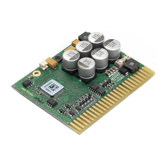
Overview Overview Introduction The SMCP33 stepper motor control is an extremely compact and cost-effective constant current final output stage with integrated closed-loop current control. Due to the great capacity and functions available, it offers designers and developers a rapid and simple method of resolving numerous drive requirements with less programming effort. - Page 6 Technical Manual SMCP33 Overview ® With dspDrive , the motor current is controlled directly by a digital signal processor. Unlike conventional ICs, which resolve the winding current measurement and the ® target current value with only 6 or 8 bit, the new dspDrive performs the entire control with a resolution of 12 bit.
-
Page 7: Commissioning
Provisions Commissioning of the SMCP33 stepper motor is described below. You will find the main "First Steps" here to start working rapidly with the SMCP33 if you are using the NanoPro software from a PC. You will find more detailed information in the separate NanoPro manual. - Page 8 Select the <Communication> tab. In the "Port" field, select the COM port to which The number of the COM the SMCP33 is connected. port to which the controller is connected can be found in the device manager of your Windows PC (System Control/System/Hardware).
-
Page 9: Connections And Circuits
Technical Manual SMCP33 Connections and circuits Connections and circuits Pin assignment SMCP33 Pin assignment Issue: V 1.4... - Page 10 Technical Manual SMCP33 Connections and circuits Description Pin no. Name Observations Mass (0 V) Operating voltage +12 V DC ... +48 V DC Mass (0 V) Motor phases; For BLDC motors: 9/10 • A = V (red) • A/ = U (yellow) 11/12 •...
-
Page 11: Smcp33-Eva Evaluation Board
It can be used for the rapid commissioning of four stepper motors via a pre-wired RS485 network and a PC connection. All inputs and outputs available in the SMCP33 are led to the outside via Phoenix Combicon connectors. In addition, an encoder or a brake can be connected. - Page 12 Technical Manual SMCP33 Connections and circuits Connection diagram Note: The connection diagram is available for download on www.nanotec.com. Issue: V 1.4...
-
Page 13: Inputs And Outputs (I/O)
Technical Manual SMCP33 Connections and circuits Inputs and outputs (I/O) Input circuits All digital inputs are designed for 5 V input signals. Note: The voltage must not exceed 5 V. It should drop below 2 V for safe switching off and be at least 4.5 V for safe switching on. - Page 14 Technical Manual SMCP33 Connections and circuits Circuitry of hall sensors in BLDC mode The hall sensors of the BLDC motor are connected as shown in the following graphic: Function of the inputs All digital inputs – with the exception of the "Clock" input in the clock directional mode –...
-
Page 15: Brake Connection
This resistor is also referred to as the "Brake resistor" because the energy usually arises from braking of the motor. This protects the SMCP33 against destruction from brief overvoltage. The rating and cooling of the resistor determines how long it can convert the overvoltage before it becomes too hot and is destroyed. -
Page 16: Encoder Connection
Stepper motor connection Connection cable The motor is connected to the SMCP33 with a 4-wire cable. Twisted wire pair cables with braided shields are recommended. Danger of electrical surges Mixing up the connections can destroy the output stage! See the data sheet of the connected stepper motor. -
Page 17: Bldc Motor Connection
Power supply connection Permissible operating voltage The permissible operating voltage of the SMCP33 stepper motor control lies within the range +12 to +48 V DC and must not exceed 50 V or undershoot 10 V. A charging condenser with minimum 4700 µF (10000 µF) must be provided for the operating voltage to prevent exceeding the permissible operating voltage (e.g. -
Page 18: 3.10 Rs485 Communication
This network connection is set up via the RS485 port. Example: Connection to SMCP33-EVA On the SMCP33-EVA motherboard shown in Section 3.2 "SMCP33-EVA evaluation board", four stepper motors can be rapidly commissioned via a pre-wired RS485 network and a PC connection. -
Page 19: Operating Modes
Technical Manual SMCP33 Operating modes Operating modes Introduction Depending on the travel profile, the motor can be operated using different operating modes. Due to the great capacity and functions available, it offers designers and developers a rapid and simple method of resolving numerous drive requirements with less programming effort. - Page 20 Technical Manual SMCP33 Operating modes Operation mode Application Clock direction mode, left Use this mode when you wish to operate the motor with a superordinate controller (e.g. CNC controller). Clock direction mode, right In the clock direction mode, the motor is operated via...
-
Page 21: Troubleshooting
Red LED on Overtemperature of power Switch off controller and allow to the SMCP33 electronics > 75 °C cool. lights up. The error is reset when the SMCP33 is disconnected from the power supply unit. Undervoltage Check voltage supply. Issue: V 1.4... -
Page 22: Technical Data
Electrical connections Operating voltage V DC 12 V to 48V ±4% Max. phase current SMCP33: nominal current 2 A, adjustable up to max. 3 A/phase SMCP33-K (with heat sink): nominal current 4 A Current drop Adjustable 0 to 100% of phase current •... - Page 23 Ambient temperature 0 to 40 °C SMCP33 dimensions SMCP33-K dimensions (with heat sink) A complete set of datasheets is available for downloading at www.nanotec.com. Mating connector/board holder, EADC types Mating connector: 345-050-521-202 Inline plug-in unit, short: 345-220-088 Encoding element between contact: 345-240-318...
- Page 24 Technical data Overtemperature protection In the SMCP33 with a heat sink, the power drive of the controller is switched off at a temperature of approx. 75 °C and is set to output 3. In the SMCP33 without a heat sink, the overtemperature protection of the driver component is activated at a temperature of approx.
- Page 25 Technical Manual SMCP33 Technical data Operating voltage 24 V (without heat sink) Operating voltage 24 V (with heat sink) Issue: V 1.4...
- Page 26 Technical Manual SMCP33 Technical data Operating voltage 48 V (without heat sink) Operating voltage 48 V (with heat sink) Issue: V 1.4...
-
Page 27: Index
External reference run ........19 Reference run ..........19 Rotation monitoring........6, 16 Hall sensors...........14 RS485 communication........18 Input circuits ..........13 SMCP33 functions .......... 5 Inputs .............14 Internal reference run ........19 Variants............5 Voltage supply ..........17 Motor connection Issue: V 1.4...
Need help?
Do you have a question about the SMCP33 and is the answer not in the manual?
Questions and answers