Table of Contents
Advertisement
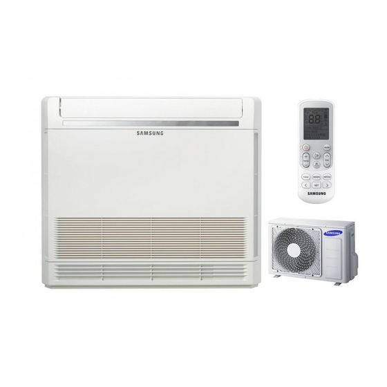
AIR CONDITIONER
AC026FBJDEH/EU
AC026FBJDEH/EU
AC035FBJDEH/EU
AC035FBJDEH/EU
AC052FBJDEH/EU
AC052FBJDEH/EU
AC026FCADEH/EU
AC035FCADEH/EU
AC052FCADEH/EU
Refer to the service manual in the GSPN(see the rear cover) for the more information.
SYSTEM AIR CONDITIONER
BASIC MODEL : JH052EAV1 / RC052DHXEA
MODEL : AC026FBJDEH / AC026FCADEH
AC035FBJDEH / AC035FCADEH
AC052FBJDEH / AC052FCADEH
MODEL CODE :
AC026FBJDEH / EU / AC026FCADEH / EU
AC035FBJDEH / EU / AC035FCADEH/ EU
AC052FBJDEH/ EU / AC052FCADEH/ EU
CONTENTS
1. Precautions
2. Product Specifications
3. Disassembly and Reassembly
4. Troubleshooting
5. PCB Diagram
6. Wiring Diagram
7. Schematic Diagram
8. Reference Sheet
Advertisement
Table of Contents
Troubleshooting

Related Manuals for Samsung AC026FBJDEH


Summarization of Contents
Precautions
Precautions for Service
Safety guidelines for service personnel, including handling parts and tools.
Precautions related to static electricity and PL
Safety measures against static electricity and potential liabilities during repair.
Precautions related to product safety
Guidelines to prevent electric shock, fire, and damage during operation and repair.
Other precautions
Additional important considerations for installation and handling, like pump down procedures.
Product Specifications
The Feature of Product
Description of key features and technologies of the air conditioner, like Console type and Virus Doctor.
Product Specifications
Detailed technical specifications including dimensions, capacity, power consumption, and sound levels.
Product Accessories and Option accessories
Lists of included accessories and optional items with their part numbers and quantities.
Disassembly and Reassembly
Indoor Unit Disassembly
Step-by-step instructions for disassembling the indoor unit components.
Outdoor Unit Disassembly
Step-by-step instructions for disassembling the outdoor unit components.
Troubleshooting
Indoor Unit Configuration and Settings
Procedures for setting indoor unit addresses and installation options using the remote controller.
General Diagnostics and Test Modes
Initial checks, error displays, test run modes, ECO mode, and wired remote controller functions.
Troubleshooting by Symptoms
Detailed diagnostic steps for common indoor and outdoor unit errors and malfunctions.
PCB Diagrams
Indoor Unit PCB Diagram
Visual layout and component identification for the indoor unit's main PCB.
Display and Damper PCB Diagrams
Diagrams showing the layout of the display PCB and the DAMPER PBA.
Outdoor Unit PCB Diagram
Diagram detailing the main PCB of the outdoor unit with numbered components.
Wiring Diagrams
Indoor Unit Wiring Diagram
Schematic showing electrical connections for the indoor unit's components.
Outdoor Unit Wiring Diagram
Schematic illustrating the electrical connections within the outdoor unit.
Schematic Diagrams
Indoor Unit Schematic Diagram
Detailed circuit diagram for the indoor unit's main PCB and connected modules.
Outdoor Unit Schematic Diagram
Detailed circuit diagrams for the outdoor unit's main and sub PCBs.
Reference Sheet
Index for Model Name
Guide to understanding the model code structure and its components.
Refrigerating Cycle Diagram
Visual representation of the refrigerant flow and key components in the system.
Pressure Graph
Graphs illustrating system pressure variations relative to outdoor and indoor temperatures.
Need help?
Do you have a question about the AC026FBJDEH and is the answer not in the manual?
Questions and answers