Table of Contents
Advertisement
AIR CONDITIONER
SYSTEM AIR CONDITIONER
4 WAY CASSETTE SERIES
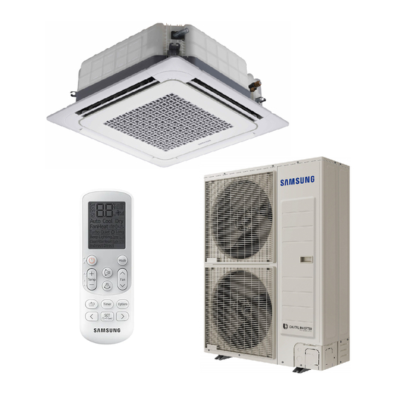
INDOOR UNIT
Model :
AC071JN4CEH
AC100JN4CEH
AC125JN4CEH
CONTENTS
1. Precautions
2. Product Specifications
3. Disassembly and Reassembly
4. Troubleshooting
5. PCB Diagram
6. Wiring Diagram
7. Reference Sheet
OUTDOOR UNIT
AC071JXSCEH
AC100JXSCEH
AC100JXSCGH
AC125JXSCGH
Advertisement
Table of Contents
Troubleshooting

Related Manuals for Samsung AC071JN4CEH


Summary of Contents for Samsung AC071JN4CEH
- Page 1 SYSTEM AIR CONDITIONER 4 WAY CASSETTE SERIES INDOOR UNIT OUTDOOR UNIT Model : AC071JN4CEH AC071JXSCEH AC100JN4CEH AC100JXSCEH AC125JN4CEH AC100JXSCGH AC125JXSCGH AIR CONDITIONER CONTENTS 1. Precautions 2. Product Specifications 3. Disassembly and Reassembly 4. Troubleshooting 5. PCB Diagram 6. Wiring Diagram...
-
Page 2: Table Of Contents
4-3-5 Indoor unit float sensor error ......................4-21 4-3-6 EEPROM circuit failure ........................... 4-22 4-3-7 Thermal Fuse Open Error ........................4-23 4-3-8 When the outdoor unit power is not ON – Initial Diagnosis (AC048JXQRHH, AC048JXQRHC): 3-phase products ......4-24 Samsung Electronics... - Page 3 6. Wiring Diagram ....................6-1 6-1 Indoor Unit ................................6-2 Outdoor Unit ................................. 7. Reference Sheet ....................7-1 7-1 Index for Model Name ............................7-1-1 Indoor Unit ..............................7-1-2 Outdoor Unit ............................. 7-1-3 Panel ................................7-2 Refrigerating Cycle Diagram .......................... Samsung Electronics...
-
Page 4: Precautions
Check whether the installation location is at least two meters away from other electronic products such as TV, video, or audio. – Otherwise, the video quality might be degraded or noise might be generated. Do not let end users repair the products themselves. – Unauthorized disassembly might cause electric shock or fire. Samsung Electronics... -
Page 5: Precautions Related To Product Safety
– Release the high pressure and low pressure valve caps. – Close the high pressure valve completely using an L-wrench – After about two minutes, close the low pressure valve completely. – Stop running the air conditioner. – Separate the connecting pipe. Samsung Electronics... -
Page 6: Product Specifications
The equipment operates with minimum power to maintain the 1°C Setting temperature optimum temperature and it always maintains a pleasant room -1°C -2°C temperature in small temperature steps of 0.1°C that you may not be able to sense. Smart inverter air conditioner General air conditioner Samsung Electronics... - Page 7 PCB option so that the unit can be installed on a ceiling with a height of 3.5 meters. [When installing on a ceiling [When installing on a ceiling of 3m or higher] of 3m or lower] Samsung Electronics...
- Page 8 - Capable of realizing optimal air current in accordance to customer preference and diverse structures located in different directions through individual control of each of the 4 blades. - Individual control can be realized through both cable and wireless remote control. Samsung Electronics...
-
Page 9: Product Specifications
Product Specifications Product Specifications 2-2 Product Specifications Development Model Item AC071JN4CEH AC100JN4CEH AC100JN4CEH AC125JN4CEH AC071JXSCEH AC100JXSCEH AC100JXSCGH AC125JXSCGH Indoor Unit Design Outdoor Unit Remote Controller Cooling [W] (Min/STD/Max) 1700/7100/8500 2200/10000/12000 2200/10000/12000 2200/12500/14000 Performance Heating [W] (Min/STD/Max) 3000/8000/11000 3300/11200/17000 3300/11200/17000 3300/14000/19000... -
Page 10: Specifications Of Optional Items
Remark Ass'y drain hose DB94-02719B Cable-tie DB65-00191A Seal-drain ass'y DB62-05810A Indoor Unit Seal-drain ass'y DB62-05810F Seal-drain ass'y DB62-05810G CARD WARRNATY DB68-02596B Rubber Leg DB73-20134A Outdoor Unit ASSY-INSTALLATION DB68-05330A MANUAL BOLT-FLANGE 6011-003975 ASSY-INSTALLATION DB68-03683A Panel MANUAL CARD WARRNATY DB68-01675A Samsung Electronics... - Page 11 Product Specifications Accessories (cont.) ■ Item Descriptions Q'TY Remark Wireless remote controller DB93-15169K Batteries for remote controller 4301-000121 (specification: AAA type) Remote controller holder DB61-06087A Optional M4×16 screw 6002-000581 User’s manual DB68-05423A Samsung Electronics...
- Page 12 Product Specifications Accessories (cont.) ■ Item Descriptions Q'TY Remark Wired remote controller DB93-11251F Cable tie DB65-10088B Cable clamp DB65-10074E Optional M4×16 Screw 6002-000474 User’s manual DB68-03732A Installation guide DB68-03716A Samsung Electronics...
- Page 13 Product Specifications Accessories (cont.) ■ Item Descriptions Q'TY Remark Central controller DB93-03425Q Cable tie DB65-10088B Cable clamp DB65-10074E Optional M4 X 16 Screw 6002-000474 User’s manual DB68-03736A Installation guide DB68-03721A Samsung Electronics...
-
Page 14: Filter Specifications
Product Specifications 2-3-2 Filter specifications Item Descriptions Remark Basic/ Dust filter DB63-03158A Water wash 2-10 Samsung Electronics... -
Page 15: Disassembly And Reassembly
Disassembly and Reassembly 3. Disassembly and Reassembly Item Remarks +SCREW DRIVER Adjustable Wrench (8mm, 10mm, 13mm) M6, M8 Hex Wrench Samsung Electronics... -
Page 16: Indoor Unit
Procedure Remark Panel 1) Push the handles on both sides of the Samsung logo towards the product’s interior to open the Grille. 2) Push up the green knob in the Open direction, and detach the white link from the panel. Detach the safety clip. - Page 17 1) Disconnect the Connector Wire that is connected to the indoor unit’s PBA from the PBA. 2) Unscrew the 2 fixed screws on both sides of the Control Box, and disassemble the Control Box from the indoor unit. (Use +Screw Driver) Samsung Electronics...
- Page 18 2) Push the Bell-Mouth in the direction opposite to where it’s installed on the Control-Box to remove it. Drain Pan 1) Unscrew the screws on the 4 corners of the indoor unit. (Use +Screw Driver) 2) Remove the Drain Pan from the indoor unit. Samsung Electronics...
- Page 19 Drain-Hose out from the indoor unit to disassemble the transparent Drain-Hose fixed on the side of the indoor unit. (Use +Screw Driver) 1) Use your hand to remove the temperature Evap. sensor attached to the Evap Pipe along with Temperature the fixing clip. Sensor Samsung Electronics...
- Page 20 1) Remove the screws of the 2 Steel Holder Evaps that are used to fix the Heat Exchanger, and then remove it. (Use +Screw Driver) 2) Remove the 2 fixing screws of the Partition Evap at the Heat Exchanger’s In/Out Pipe. (Use +Screw Driver) Samsung Electronics...
- Page 21 Disassembly and Reassembly Parts Procedure Remark 3) Remove the screw of the Cover Pipe that is used to fix the In/Out Pipe. Remove the In/Out Pipe. (Use +Screw Driver) 4) Remove the Heat Exchanger from the indoor unit’s cabinet. Samsung Electronics...
- Page 22 1) loosen 1 pcs screw of cover control,and detach it. 2) loosen 5 pcs screws on both right and left cabniet side edges and to detach the cover-top 3) Loosen 7 screwsfixed to disassemble cabi-front , and detach it. Samsung Electronics...
- Page 23 Disassembly and Reassembly Parts Procedure Remark common work 4) loosen 7 screws to disassemble the cabi- right ,and detach it. 5) loosen 2 screws to disassemble steel-bar. 6) loosen 3 screws to disassemble cabi-left. Samsung Electronics...
- Page 24 Remark fan&motor 1) loosen 1 screw as indication and detached the fan. 2) loosen 4 pcs motor screws and disconnect the wire betwwen assy control out and motor. 3) loosen 2 pcs bracket-motor screw and detach it. 3-10 Samsung Electronics...
- Page 25 Heat exchanger 1) Release the refrigerant at first 2) Looosen fixing screw on both side. 3) disaessembly the pipes in both inlet and outlet with welding torch. 4) detach the heat exchanger. Samsung Electronics 3-11...
- Page 26 Disassembly and Reassembly Parts Procedure Remark compressor 1) disconnect the compressor lead wire . 2)disassembly the felt comp sound. loosen the 3 bolts at the bottom of 3-12 Samsung Electronics...
- Page 27 Cabinet Front RH. (Use +Screw Driver) Cabi Top 1) Unscrew and remove 9 screws on each side of the Cabinet-Top. (Use +Screw Driver) Cabi Install Front 1) Unscrew and remove 1 screw in the Cabinet-Install Front. (Use +Screw Driver) Samsung Electronics 3-13...
- Page 28 2) Unscrew and remove 4 screws in the Guard Cond. (Use +Screw Driver) Cabi Back RH 1) Pull the sensor from Cabi Back RH. 2) Unscrew and remove 4 screws on each side of the Cabinet Back RH. (Use +Screw Driver) 3-14 Samsung Electronics...
- Page 29 Disassembly and Reassembly Parts Procedure Remark Cabi Install Back 1) Unscrew and remove 1 screw in the Cabinet-Install Back. (Use +Screw Driver) Cabi Front LF 1) Unscrew and remove 10 screws in the Cabinet-Front LF. (Use +Screw Driver) Samsung Electronics 3-15...
- Page 30 Disassembly and Reassembly Parts Procedure Remark 1) Turn 2 mounting nuts as shown in the picture and remove it. (Use Adjustable Wrench) 3-16 Samsung Electronics...
- Page 31 1) Separate the Fan Propeller. 2) Unscrew and remove the 8 Motor mounting screws. (Use +Screw Driver) 3) Disconnect the Motor wire From Ass'y Control Out. Bracket Motor 1) Unscrew and remove 2 mounting screws in Bracket Motor. (Use +Screw Driver) Samsung Electronics 3-17...
- Page 32 Disassembly and Reassembly Parts Procedure Remark Control Out 1) Disconnect 4 Connecters From Ass'y Control Out. 2) Unscrew and remove 1 mounting screw in Control Out. (Use +Screw Driver) 3) Separate Ass'y Control Out. 3-18 Samsung Electronics...
- Page 33 Service Valve. (Use +Screw Driver) 4) Separate the pipe from the Entrance/Exit using a welder. When removing the compressor, Heat Exchanger, and Pipe, purge the Coolant inside the Compressor completely and remove the pipe with a welding flame. Samsung Electronics 3-19...
- Page 34 1) Unscrew and remove 2 mounting screws in Service Valve. (Use +Screw Driver) 2) Separate the pipe from the Entrance/Exit using a welder. Compressor 1) Unscrew and remove 1 mounting nut in Cover Terminal. (Use Adjustable Wrench) 2) Separate the Compressor Felt Sound. 3-20 Samsung Electronics...
- Page 35 3) As shown in the picture, unscrew and remove 3 mounting screws from the bottom. (Use Adjustable Wrench) Cond Out 1) Unscrew and remove 3 screws on each side of the Assy Cond Out. (Use +Screw Driver) 2) Separate the Compressor Felt Sound. Samsung Electronics 3-21...
-
Page 36: Outdoor Unit
Cabi Install Front 1) Unscrew and remove 1 screw in the Cabinet-Install Front. (Use +Screw Driver) Guard Cond 1) Pull the sensor from Guard Cond. 2) Unscrew and remove 4 screws in the Guard Cond. (Use +Screw Driver) 3-22 Samsung Electronics... - Page 37 Cabinet Back RH. (Use +Screw Driver) Cabi Install Back 1) Unscrew and remove 1 screw in the Cabinet-Install Back. (Use +Screw Driver) Cabi Front LF 1) Unscrew and remove 10 screws in the Cabinet-Front LF. (Use +Screw Driver) Samsung Electronics 3-23...
- Page 38 2) Remove the Cover from the Fan Propeller 3) Turn 2 mounting nuts as shown in the picture and remove it. (Use Adjustable Wrench) When you assemble the Fan Propeller and the Cover, must check the rib in the hole. 3-24 Samsung Electronics...
- Page 39 1) Unscrew and remove 2 mounting screws in Bracket Motor. (Use +Screw Driver) Heater 1) Unscrew and remove 4 screws on the Base Out. (Use +Screw Driver) 2) Disconnect the heater wire from the Ass'y Control Out. Samsung Electronics 3-25...
- Page 40 Coolant inside the Compressor completely and remove the pipe with a welding flame. Assy EEV Valve 1) Unscrew and remove 2 mounting screws in Service Valve. (Use +Screw Driver) 2) Separate the pipe from the Entrance/ Exit using a welder. 3-26 Samsung Electronics...
-
Page 41: Troubleshooting
After entering the option setting status, select the option as listed below. On(SEG1~12) Off(SEG13~24) SEG1 SEG2 SEG3 SEG4 SEG5 SEG6 SEG7 SEG8 SEG9 SEG10 SEG11 SEG12 SEG13 SEG14 SEG15 SEG16 SEG17 SEG18 SEG19 SEG20 SEG21 SEG22 SEG23 SEG24 Samsung Electronics... - Page 42 Press Mode button to be changed to AUTO mode in the OFF status. 11. Setting SEG14, SEG15 option Press Low Fan button( ) to enter SEG14 value. Press High Fan button( ) to enter SEG15 value. Each time you press the button, … will be selected in rotation. SEG14 SEG15 Samsung Electronics...
-
Page 43: The Procedure Of Setting Option
Press Mode button to be change to HEAT mode in the OFF status. 19. Setting SEG23, SEG24 mode Press Low Fan button( ) to enter SEG23 value. Press High Fan button( ) to enter SEG24 value. Each time you press the button, … will be selected in rotation. SEG23 SEG24 Samsung Electronics... - Page 44 Step 5. Check operation 1) Reset the indoor unit by pressing the RESET button of indoor unit or outdoor unit. 2) Take the batteries out of the remote controller and insert them again and then press the operation button. Samsung Electronics...
-
Page 45: Order For Setting Options (Wired Remote Controller)
Press the Set button to save the settings and exit to the sub-menu setting screen. Press the button to exit to normal mode. ]/[ ] buttons to set the range of Data bit. button to exit to the setting sub-menu without saving your changes. Samsung Electronics... -
Page 46: Setting An Indoor Unit Installation Option (Suitable For The Condition Of Each Installation Location)
If you input a number other than 0~4 of the individual control of the indoor unit(SEG20), the indoor is set as indoor 1. ▶ 4WAY MODEL : Even when the value of Heating setting compensation(SEG21) is set to '0' , it wil be recognized as '5°C' . Samsung Electronics... - Page 47 Individual control of a Heating setting Explanation PAGE remote controller compensation Remote Controller Display RESERVED RESERVED RESERVED Indication Details Indication Details Indication Details 0 or 1 Indoor 1 Disuse Indication Indoor 2 and Details 2°C Indoor 3 5°C Indoor 4 Samsung Electronics...
-
Page 48: Changing A Particular Option
SEG3 SEG4 SEG5 SEG6 The option The tens’ digit of The unit digit of The changed Explanation PAGE MODE mode you want an option SEG an option SEG value to change you will change you will change Indication Samsung Electronics... -
Page 49: Option Code For Each Model
Troubleshooting 4-1-6 Option code for each model Model SEG1 SEG2 SEG3 SEG4 SEG5 SEG6 SEG7 SEG8 SEG9 SEG10 SEG11 SEG12 Remocon display AC071JN4CEH AC100JN4CEH AC125JN4CEH Model SEG13 SEG14 SEG15 SEG16 SEG17 SEG18 SEG19 SEG20 SEG21 SEG22 SEG23 SEG24 Remocon display... -
Page 50: Items To Check Before Diagnostics
Ver.3( Short press once after Ver.2) E2P version Year (Hex) Month (Hex) Date (Two digits) Date (One digit) ※ Press the K4 button long (Main MICOM version) Press once more shortly Press shortly one more time (E2P version) 4-10 Samsung Electronics... - Page 51 Set an auto address. Set a manual address. Snowdrift prevention control not used. Snowdrift prevention control used. Silent control not used Silent control used Step_1 Silent control used Step_2 Silent control used Step_3 Auto silent mode Manual silent mode Samsung Electronics 4-11...
- Page 52 Segment 3 Segment 4 Eco Mode BLANK BLANK BLANK BLANK Press K3 to go out from the eco mode. Eco Mode Exit At the driving signal or test run (cooling/heating) of the user, the mode is released. 4-12 Samsung Electronics...
-
Page 53: Four Directions Cassette Type
EEPROM component. EEPROM error operation- operation- operation- set the options. EEPROM option error between indoor and outdoor machine models Outdoor valve clogging operation- operation- operation- error. clogging. : On : Blink X : Off Samsung Electronics 4-13... -
Page 54: Wired Remote Controller
Operation Off protection error compressor. control error Outdoor unit Check the input power [Inverter] Total current error/ Operation Off protection Check the coolant charging status PFC over current error control error Check the normal operation of outdoor fan 4-14 Samsung Electronics... - Page 55 Replace the PBA of the outdoor unit. Check the coolant charging status Check the indoor EVA sensor Self diagnostic Gas leak error Check if the outdoor unit service value is open Operation Off error Check that the indoor/outdoor installation pipe/wiring are correct Samsung Electronics 4-15...
- Page 56 Wired remote Normal operation error COM2 terminal of the indoor unit controller error Wired remote controller COM2 Wired remote Check that Com1, Com2 setting DIP switch is set to Com2 Normal operation option setting error controller error 4-16 Samsung Electronics...
-
Page 57: Troubleshooting By Symptoms
In this case, is the resistance 8.300 value out of range in the temperature table on the right? 10.00 12.10 Indoor temperature sensor 14.70 failure (replace) 18.00 Restart the system after replacing the PCB 22.00 28.30 33.90 42.30 Samsung Electronics 4-17... -
Page 58: Indoor Heat Exchanger Temperature Sensor (Open/Short)
In this case, is the resistance 8.300 value out of range in the temperature table on the right? 10.00 12.10 Failure of the indoor heat 14.70 exchanger temperature sensor (replace) 18.00 Restart the system after replacing the PCB 22.00 28.30 33.90 42.30 4-18 Samsung Electronics... - Page 59 DC 0V~DC 6V is output. Is the RPM of motor less ↓ ↓ 2 3 4 than 120? Motor Is voltage of DC 0V~DC 6V displayed? Check the motor and Check the PCB and replace it. replace it Samsung Electronics 4-19...
-
Page 60: Communication Error After Finishing Tracking
PCB and replace the PCB Reconnect the cable connecting the outdoor unit to the indoor unit and restart the unit. If the communication still doesn’t work, replace the indoor unit PCB. Good +0.7V -0.7V 4-20 Samsung Electronics... -
Page 61: Indoor Unit Float Sensor Error
Drain pump PCB Is the terminal voltage around AC 220V? Is the water level in drain pan decreasing? Replace the drain pump Replace the indoor unit PCB Normal operation Replace the drain pump when the indoor power is reset Samsung Electronics 4-21... -
Page 62: Eeprom Circuit Failure
EEPROM component failure, EEPROM circuit parts missing/damaged/soldering failure Power on. E162 occurs. Are EEPROM SUM PBA correctly assembled? Reassemble EEPROM PBA. Is there a problem in soldering failure or short of between EEPROM PIN? Remove short or soldering failure. Replace EEPROM PBA. 4-22 Samsung Electronics... -
Page 63: Thermal Fuse Open Error
(Temperature rise by untightening a screw/ Termal Fuse open E198 occurs. Is the CN140 connector of PCB between wire correctly connected? Re-operation after the connector. Measure both ends of connector connected the TERMINAL BLOCK. Paragraph (Short) Has the connector ends? Replace the MAIN PBA. Samsung Electronics 4-23... - Page 64 1. Connect the power supply. 1. Is there a fault in the connection 2. Turn on the terminal box and check whether of the power supply to Main PBA normal power is supplied to the outdoor unit. and EMI PBA? Continued 4-24 Samsung Electronics...
- Page 65 2. Check whether the power of the outdoor unit during power supply, the motor can be damaged.) is supplied by powering on the terminal box. If it is normal, replace the fan motor. Outdoor inverter PBA checking part Fan Motor Connector Samsung Electronics 4-25...
- Page 66 1. Is there a fault in the connection of the 2. Check whether the power of the outdoor unit power supply to Main PBA is supplied by powering on the terminal box. and EMI PBA? RC072DHXB Series ignored Continued 4-26 Samsung Electronics...
- Page 67 If it is normal, replace the fan motor. Outdoor inverter PBA Indoor control PBA checking part checking part Fan Motor Connector [RC090/100/125/140/145 HXE , [RC072DHXB ] RC100DHXB ] Samsung Electronics 4-27...
- Page 68 PBA of the outdoor unit. Replace the main PBA of the outdoor unit. 1. Is there a problem in communication IC? 2. Is there a fault in TVS-Diode? Fault checking part Communication IC Communication TVS-Diode TVS-Diode [RC090/100/125/140/145 HX [RC072DHXB ] Continued 4-28 Samsung Electronics...
- Page 69 COM 1(RED) #6 - #5 0.9kΩ ~ 1.2kΩ Measuring after separating the communication #7 - #5 0.9kΩ ~ 1.2kΩ connection #8 - #5 4.7Vdc ~ 5.3Vdc TVS-Diode Measuring Steady-state Measuring Value Both ends of diode 1kΩ or above Samsung Electronics 4-29...
- Page 70 The outdoor unit inverter PBA is normal. (CN31) Main PBA connecting part (CN39) [Main PBA 7-segment HXG , RC145DHXH , HX , RC100DHXB , AC100FCA GH Inverter PBA LED FCA EH Inverter PBA LED confirming part (Common)] confirming part ] confirming part] 4-30 Samsung Electronics...
- Page 71 (°C) After confirming the state is normal, Does the same error occur again end the service. after power is on? Replace the outdoor unit PBA. Power is on. After confirming the state is normal, end the service. Samsung Electronics 4-31...
- Page 72 If the error is indicated on 7-segment of the main PBA of the outdoor unit, the main PBA of the outdoor unit has no fault. In case of a control problem, it is possible to solve with S/W update. 4-32 Samsung Electronics...
- Page 73 3. Is there abnormal noise 3. Compressor replacement: Serious abnormal in the rotation of the compressor? noise (Metallic scraping or grinding noise), serious vibration s the resistance between Replace the compressor. the compressor body and the chassis Mega Ω? Continued Samsung Electronics 4-33...
- Page 74 Because it is an error regarding the inverter PBA, it is not related to the aforementioned PBA. Ensure that the service valve is open! While the service valve is closed and the COMP. starts, it is possible to cause a fault due to differential pressure. PBA connecting connector COMP connecting connector [RC072DHXB ] 4-34 Samsung Electronics...
- Page 75 2. Remove the obstacles of the outlet and secure the space. Has the service valve been completely open? Open the valve. Does the compressor work correctly? Replace the compressor. After replacing the inverter PBA of the outdoor unit, check normal startup. End the service. Samsung Electronics 4-35...
- Page 76 2. Remove the obstacles of the outlet and secure the space. Re-install correctly under the product Have the pipes and wires of indoor and specifications. outdoor units been correctly installed? Continued Pipe Poor installation Wire 4-36 Samsung Electronics...
- Page 77 Is the resistance between the compressor Replace the compressor. body and the chassis Mega Ω? After power is off, Are the position and measuring value of correct or replace the sensor position. the temperature sensor normal? Continued Samsung Electronics 4-37...
- Page 78 E464 Error-related, EMI / outdoor unit Main / Indoor unit Main PBA do not AC100FCA GH] replace! This error is related to the compressor and Inverter PBA. (Not related to the above PBA) COMP connecting PBA connecting connector connector [RC072DHXB Series] 4-38 Samsung Electronics...
- Page 79 Check the normal operation the reactor or broken or Shut down the service loosened terminal? HXG , RC145DHXH , AC100FCA GH Confirmation Matters] [RC090/100/125/140 HXE , RC100 HXB , AC FCA EH Confirmation Matters] [RC072DHXB Confirmation Matters] Continued Samsung Electronics 4-39...
- Page 80 2. Connect the terminal of the power terminal box and the power cable. Check normal assembled? startup. End the service. After replacing the inverter PBA of the outdoor unit, check normal startup. End the service. 4-40 Samsung Electronics...
- Page 81 (Metallic scraping or grinding noise), compressor? serious vibration Re-install correctly under Have the pipes and wires of indoor and the product specifications. outdoor units been correctly installed? Poor installation Pipe Continued Wire Samsung Electronics 4-41...
- Page 82 Troubleshooting (Continued) Continued Has the service valve been completely Open the valve. opened? Re-connect the sensor connector. Is the indoor EVA sensor correctly connected? Charge the refrigerant. Has the refrigerant been charged? Replace the inverter PCB. 4-42 Samsung Electronics...
- Page 83 After that, the refrigerant leakage. recharge. Check the temperature value through Check the fault in the indoor unit EVA S-NET, etc. and then if there is a fault, replace sensor and the connection state. and reconnect. Samsung Electronics 4-43...
- Page 84 11. IPM (IGBT Module) or PFCM temperature sensor error: E474 IPM overheat error for outdoor unit inverter compressor: E500 - Check whether IPM is correctly assembled on the heatproof plate. - Check whether the inlet is blocked. - If there is a defect, replace IPM. 4-44 Samsung Electronics...
-
Page 85: Pcb Diagram And Parts List
5. PCB Diagram and Parts List 5-1 Indoor Unit 5-1-1 MAIN PCB 21 23 This Document can not be used without Samsung’s authorization. Samsung Electronics... - Page 86 #1:INDOOR THERMISTOR #1~#4: EEV SIGNAL OUTPUT #1:DC12V #1 : DC12V #2~#5: L OUVER SIGNAL #5: DC12V #2~#5: LOUVER SIGNAL OUTPUT #2~#5: L OUVER SIGNAL OUTPUT #2:GND OUTPUT #6:DC12V #6 : DC12V #7~#10: L OUVER SIGNAL OUTPUT ㉑ (21) CN801-SPI ㉒ TB101-AC POWER ㉓ TE04-COMMUNICATION #1: GND #1: POWER(L) #1: COM1(F1) #2: GND #2: POWER(N) #2: COM1(F2) #3: SPI SIGNAL OUTPUT(DC12V) #3: V1(DC12V) #4: V2(GND) #5: COM2(F3) #6: COM2(F4) Samsung Electronics...
-
Page 87: Panel Pcb
PCB Diagram and Parts List 5-1-2 Panel PCB ① CN01-DISPLAY #1 : DC12V #2~6 : LED Control Signal #7 : Not used #8 : Remocon Signal Out #9 : Not used #10 : Remocon Signal In #12 : Vcc #13 : Not used This Document can not be used without Samsung’s authorization. Samsung Electronics... -
Page 88: Outdoor Unit
SMW250-06 WHT 3711-000939 CN801 ERROR/COMP CHECK SMW250-04 RED 3711-000176 CN12 DC12V YW396-02V BLU 3711-000997 CN803 EEV1 SMW250-05 BLU 3711-001036 CN802 EEV4 SMW250-06 BLU 3711-001084 CN403 OUT TEMP/COND/DISQ/OLP SMW250-08 WHT This Document can not be used without Samsung’s authorization. Samsung Electronics... -
Page 89: Inverter Pcb
#Reactor-B2 : BLK #3 : GND, #4 : DC 5V #3, #8 : N.C, #4~#7 : DATA signal #5 : DC 12V, #6 : INV. SMPS signal #9 : GND, #10 : DC 5V ⑤ ⑥ ⑦ ⑧ CN21-DAC/ENCODER CN91-FAN2 CN90-FAN1 CN71-COMP. For S/W engineer debugging #1 : DC 360V #1 : DC 360V #1 : COMP. U-phase(RED) #2 : N.C #2 : N.C #2 : COMP. V-phase(BLU) #3 : GND #3 : GND #3 : COMP. U-phase(YEL) #4 : DC 15V #4 : DC 15V #5 : FAN RPM #5 : FAN RPM #6 : FAN RPM feedback #6 : FAN RPM feedback This Document can not be used without Samsung’s authorization. Samsung Electronics... - Page 90 #3 : COMP. W-phase(YEL) #4 : DC 15V #4 : DC 15V #5 : FAN RPM #5 : FAN RPM #6 : FAN RPM feedback #6 : FAN RPM feedback This Document can not be used without Samsung’s authorization. Samsung Electronics...
- Page 91 #3 : GND, #4 : DC 5V #3, #8 : N.C, #4~#7 : DATA signal #T : AC 380~400V : BLK #5 : DC 12V, #6 : INV. SMPS signal #9 : GND, #10 : DC 5V ⑤ ⑥ ⑦ ⑧ CN21-DAC/ENCODER CN91-FAN2 CN90-FAN1 CN800-COMP. For S/W engineer debugging #1 : DC 360V , #2 : N.C #1 : DC 360V, #2 : N.C #1 : COMP. U-phase(RED) #3 : GND, #4 : DC 15V #3 : GND, #4 : DC 15V #2 : COMP. V-phase(BLU) #5 : FAN RPM, #6 : FAN RPM feedback #5 : FAN RPM, #6 : FAN RPM feedback #3 : COMP. U-phase(YEL) ⑨ CN600-REACTOR #1-#2 : DCL Reactor This Document can not be used without Samsung’s authorization. Samsung Electronics...
-
Page 92: Emi Pcb
PCB Diagram and Parts List 5-2-3 EMI PCB AC071JXSCEH, AC100JXSCEH ① ② ③ L1-AC POWER L phase N1-AC POWER N phase CN01-AC POWER L1 : BRN N1 : SKY-BLU #1-#3 : AC 220~240V This Document can not be used without Samsung’s authorization. Samsung Electronics... - Page 93 PCB Diagram and Parts List AC100JXSCGH, AC125JXSCGH ① ② RST-AC POWER 3phase CN100-AC POWER #R : AC 380~400V : WHT #1-#3 : AC 220~240V #S : AC 380~400V : BRN #T : AC 380~400V : BLK This Document can not be used without Samsung’s authorization. Samsung Electronics...
-
Page 94: Heater Pcb
② AC POWER OUTPUT #1 AC POWER LINE - LIVE #1 AC POWER LINE - LIVE #2 AC POWER LINE - NEUTRAL #2 AC POWER LINE - NEUTRAL This Document can not be used without Samsung’s authorization. 5-10 Samsung Electronics... -
Page 95: Wiring Diagram
6. Wiring Diagram 6-1 Indoor Unit This Document can not be used without Samsung’s authorization. Samsung Electronics... -
Page 96: Outdoor Unit
6-2 Outdoor unit AC071JXSCEH, AC100JXSCEH Samsung Electronics... - Page 97 Outdoor Unit (cont.) AC100JXSCGH, AC125JXSCGH This Document can not be used without Samsung’s authorization. Samsung Electronics...
-
Page 98: Reference Sheet
COOLING ONLY PREMIUM HEAT PUMP R410a DELUXE <- Basic HEAT RECOVERY STANDARD COOLING ONLY Low Temp. HEAT PUMP Cooling only R134A Heat Pump ※ "/" can be removed from the buyer card if there are not enough digits. Samsung Electronics... -
Page 99: Outdoor Unit
HEAT RECOVERY STANDARD COOLING ONLY UNIVERSAL HEAT PUMP DELUXE + Low Tepm. Cooling only R134A Heat Pump ★ ※ MCD: Dummy mock-up model ※ “/” can be removed from the buyer card if there are not enough digits. Samsung Electronics... -
Page 100: Panel
8 Languages English ★ Only display the Global 4 way with Korean/ English K separator. Pattern Waffle Stripe Korean Global market use 4 Way Export/ Panel foreign market use ※ Model name for the column/bundle packaging is “~S”. Samsung Electronics... -
Page 101: Refrigerating Cycle Diagram
You can open the valve by turning the need valve counterclockwise using hex wrench, and it is used for vacuum, gas purging, coolant injection, coolant purging, and indoor-outdoor unit connection. ■ ACCUMULATOR Accumulator prevents the flow of liquid-state coolant into the compressor. (Liquid-state coolant flowing into the compressor will overload the compressor.) Samsung Electronics... -
Page 102: Samsung Electronics
China china.samsungportal.com © Samsung Electronics Co., Ltd. March. 2015. This Service Manual is a property of Samsung Electronics Co., Ltd. Printed in Korea. Any unauthorized use of Manual can be punished under applicable International and/or domestic law. Code No. AC-00109E_1...
Need help?
Do you have a question about the AC071JN4CEH and is the answer not in the manual?
Questions and answers