Table of Contents
Advertisement
SERVICE
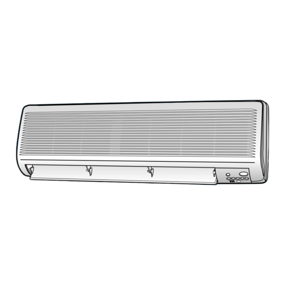
AIR CONDITIONER
ROOM AIR CONDITIONER
INDOOR
AQT24A(B)5(6)RE/B
AQT18A(B)9(0)RE/B
AQ18A(B)9(0)RE
SH24AT(B)5
SH18ZA(B)9
AQT24A(B)5(6)RED
AQ18A(B)9(0)RE(B)D
SH24TA(B)6D
SH18ZA(B)0D
AQT24C5(6)RE/B
AQT18C9(0)RE/B
AQ24A(B)5(6)RBD
AQT18C9(0)REF
Manual
1. Precautions
2. Product Specifications
3. Operating lnstructions and
Installation
4. Disassembly and Reassembly
5. Troubleshooting
6. Exploded Views and Parts List
7. Block Diagrams
8. PCB Diagrams
9. Wiring Diagrams
10. Schematic Diagrams
OUTDOOR
UQT24A(B)5(6)RE/B
UQT18A(B)9(0)RE/B
UQ18A(B)9(0)RE
SH24TA(B)5X
SH18ZA(B)9X
UQT24A(B)5(6)RED
UQ18A(B)9(0)RE(B)D
SH24TA(B)6DX
SH18ZA(B)0DX
UQT24C5(6)RE/B
UQT18C9(0)RE/B
UQ24A(B)5(6)RBD
UQT18C9(0)REF
CONTENTS
Advertisement
Table of Contents

Related Manuals for Samsung SH24TA6DX


Summarization of Contents
Room Air Conditioner
General Safety Precautions
Important safety guidelines and warnings to follow before and during air conditioner repair and operation.
Product Specifications
Performance, Electrical, and Feature Specifications
Details on cooling/heating capacity, electrical ratings, features, and refrigerant information.
Unit Dimensions and Weight
Specifications for indoor and outdoor unit dimensions, package sizes, and weight.
Major Component Specifications
Indoor and Outdoor Unit Component Details
Specifications for key components like PCB, fan motor, compressor, and heat exchanger for both units.
Unit Dimensions
Indoor and Outdoor Unit Dimensions
Diagrams and measurements for indoor, 24K BTU outdoor, and 18K BTU outdoor units.
Pressure Graphs
Pressure vs. Temperature Characteristics
Graphs showing low pressure versus outdoor air temperature for 24K BTU and 18 BTU models.
Operating Instructions and Installation
Remote Controller Functions and Operation Modes
Explanation of remote controller keys, operating modes, and fan speed settings.
Advanced Operation and Self-Diagnosis
Covers compulsory operation, swing, timers, and self-diagnosis indicators.
Installation Guidelines
Criteria for selecting installation areas and requirements for indoor and outdoor units.
Disassembly and Reassembly
Indoor Unit Disassembly Procedures
Step-by-step instructions for disassembling the indoor unit, starting with the front grille.
Outdoor Unit Disassembly Procedures
Step-by-step instructions for disassembling the outdoor unit, including cabinet and fan motor.
Troubleshooting
Initial Checks and Common Issues
Checks for voltage, cable connections, and common operational problems with explanations.
Fault Diagnosis by Symptom
Troubleshooting flowcharts for specific issues like no power, fan failure, and unit non-operation.
PCB Module Replacement
PCB Replacement and Model Option Setup
Procedure for replacing the main PCB module and setting model options via the remote control.
PCB Inspection and Part Replacement
Cautions and Procedures for Part Replacement
Guidelines for safe part replacement, including static precautions, handling, and soldering.
Detailed Troubleshooting Procedures
Specific checks and causes for malfunctions like compressor operation and voltage issues.
Exploded Views and Parts List
Indoor Unit Exploded View and Parts
Diagram showing the assembly of the indoor unit with numbered parts and a corresponding list.
Outdoor Unit Exploded Views and Parts
Diagrams showing the assembly of 18K BTU and 24K BTU outdoor units with numbered parts.
Remote Control and PCB Box Parts
Parts list and diagrams for the remote control unit and its PCB.
Block Diagrams
Refrigerating Cycle Diagram
Schematic representation of the refrigerant flow through indoor and outdoor units.
PCB Diagrams
Indoor Unit Main PCB and Component Layout
Detailed layout and component identification for the main PCB of the indoor unit.
Display and Module PCB Diagrams
Diagram and parts list for the ASS'Y DISPLAY & MODULE PCB.
Wiring Diagrams
Indoor Unit Wiring Diagram
Schematic showing electrical connections for the indoor unit, including terminal blocks and components.
Outdoor Unit Wiring Diagrams
Schematics illustrating the electrical connections for the outdoor unit and its various models.
Schematic Diagrams
Indoor Unit Schematic Diagram
Detailed circuit schematic for the indoor unit, showing component interconnections and logic.
Need help?
Do you have a question about the SH24TA6DX and is the answer not in the manual?
Questions and answers