
Related Manuals for Samsung SH18AP0D


Summary of Contents for Samsung SH18AP0D
-
Page 1: Table Of Contents
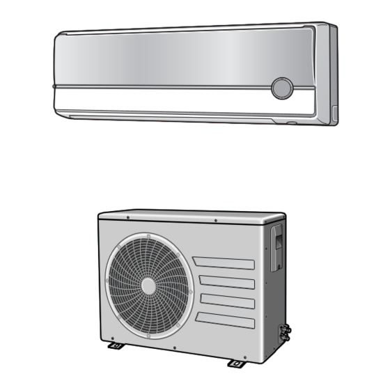
ROOM AIR CONDITIONER INDOOR UNIT OUTDOOR UNIT SH18AP0D SH18AP0DX SH24AP6D SH24AP6DX Manual SERVICE AIR CONDITIONER CONTENTS 1. Product Specifications 2. Operating Instructions & Installation 3. Disassembly and Reassembly 4. Refrigerating Cycle Diagram 5. Set Up the Model Option 6. Troubleshooting 7. -
Page 2: Product Specifications
1. Product Specifications 1-1 Table Model SH18AP0D SH24AP6D Item Cool Heat Cool Heat Power Source 220-240V~,50Hz 220-240V~,50Hz Capacity Performance Air Circulation (High) /min 13.0 13.5 14.0 14.5 Moisture Removal (High) Available Voltage Range 198~264 198~264 Running Amperes 10.8 11.2 Power Input 1.81... -
Page 3: Pressure Graph
1-2 Pressure Graph 18K BTU 32.4/24.0 30.6/22.5 28.8/21.0 27.0/19.0 24.0/17.0 21.5/15.0 Outdoor inlet air D.B. temp.(˚C) 24K BTU 32.4/24.0 30.6/22.5 28.8/21.0 27.0/19.0 24.0/17.0 21.5/15.0 Outdoor inlet air D.B. temp.(˚C) Samsung Electronics... -
Page 4: Operating Instructions & Installation
If you wish to save energy when using your air conditioner, select the Energy saving mode with the button. Sleep button. The sleep timer can be used when you are cooling or heating your room to switch the air conditioner off automatically after a period of 6 hours. Samsung Electronics... - Page 5 After setting On Timer or Off Timer, press the button to set it completely. And press the button again to cancel On Timer or Off Timer set. Digital On/Off button. If you want to turn off the display during operation press the button. Samsung Electronics...
- Page 6 Room Temperature Operating Mode Temperature Setting heat exchanger temperature and accumulating time of Less than 21˚C Heat 22˚C approx. compressor's operation. 21˚C or above Cool 24˚C approx. Deice ends by sensing of the processing time by deice condition. Samsung Electronics...
- Page 7 The air conditioner can generate anion with an ionizer in 13. BUZZER SOUND : Whenever the On/Off button is the indoor unit. pressed or whenever change occurs to the condition which is set up or select, the compulsory operation mode, buzzer is sounded "beep". Samsung Electronics...
-
Page 8: Installation Procedure
Electric and earth work shall meet the "Electric Facility Technology Standard" and the "Internal Wire Regulation" of the Electric Business Laws. I Inspection & Trial Run Upon completion of the tests, you shall make a trial run while you explain the main functions of the air conditioner to finish the installation. Samsung Electronics... -
Page 9: Installation Diagram Of Indoor Unit And Outdoor Unit
3-Way valve. And mount the service port cap to 3-Way valve. (gas) 7) Check for gas leakage. - At this time, especially check for gas leakage from the 3-Way valve’s stem nuts, (liquid) and from the service port cap. Valve stem Stem cap Samsung Electronics... - Page 10 7) Stop operation of the air conditioner. 8) Close the 3-Way valve, disconnect the pressure gauge, and open the 3-Way valve again. 9) Close the cap of each valve. Samsung Electronics...
- Page 11 • Make sure you do not bend the connection pipes in the middle and store together with the cables. • Move the indoor and outdoor units to a new location. • Remove the mounting plate for the indoor unit and move it to a new location. Samsung Electronics...
-
Page 12: Disassembly And Reassembly
10) In order to disassemble the Panel Grille, press, in order, the left, center, and right of the upper side of the Panel Grille with the palm of the hand to remove the hook. And then disassemble the Panel Grille. Samsung Electronics... - Page 13 1) Loosen 2 fixing earth screws of right side. Heat Exchanger 2) Detach the Connection Pipe. 3) Detach the Holder Pipe at the rear side. 4) Loosen 2 fixing screws of right and left side. 5) Detach the Heat Exchanger from the indoor unit. Samsung Electronics...
- Page 14 1) Loosen 4 fixing screws and detach the Fan Motor Motor Holder. & 2) Loosen 1 fixing screw of Fan Motor. Cross Fan (with a M6 wrench) 3) Detach the Fan Motor from the Fan. 4) Detach the Fan from the left Holder Bearing. Samsung Electronics...
- Page 15 Common Work Control. 2) Loosen the fixing screws of the Cabinet-Upper. 3) Loosen the fixing screws of the Cabinet-Side RH. 4) Loosen the fixing screws of the Cabinet-Side LF. 5) Loosen the fixing screws of the Ass'y Control Out. Samsung Electronics...
- Page 16 1) Loosen the Terminal Cover to open the Terminal Cover. 2) Disassemble the Cloth Sound Felt. 3) Disassemble the pipe in both inlet and outlet of the Compressor with welding torch. 4) Loosen 3 bolts at the bottom. 5) Detach the Compressor. Samsung Electronics...
-
Page 17: Refrigerating Cycle Diagram
4. Refrigerating Cycle Diagram Outdoor Unit Indoor Unit Capillary tube 2-Way valve Liquid side Heat Heat Exchanger Exchanger Gas side 3-Way valve 4-Way valve Cooling Heating Compressor Gas leak check point Samsung Electronics... -
Page 18: Set Up The Model Option
✳ Setting is not required if you must Push the button to set the display panel to Every time you push the button, the display panel reads a value which has a default..repeatedly. Samsung Electronics... - Page 19 If all lamps of indoor unit are flickering, Plug out, plug in power plug again and press ON/OFF key to retry. If the unit is not working properly or all lamps are continuously flickering after setting the option code, see if the correct option code is set up for its model. Samsung Electronics...
- Page 20 Set up the Model Option I OPTION ITEMS REMOCON SEG1 SEG2 SEG3 SEG4 SEG5 SEG6 SEG7 SEG8 SEG9 SEG10 SEG11 SEG12 MODEL SH18AP0D SH24AP6D Samsung Electronics...
-
Page 21: Troubleshooting
The compressor operates in a reverse cycle to remove Indoor fan and outdoor fan stop operation intermittently exterior ice in a HEAT mode, and indoor fan and outdoor fan in a HEAT mode. do not operate intermittently for within 20% of the total heater operation Samsung Electronics... - Page 22 Problem with the outdoor unit or PCB outdoor unit remote control. • In 3 minutes, check the voltage No power source Problem with the relay (RY71) or PCB between the indoor unit terminal displayed. block N(1) and 1. Samsung Electronics...
-
Page 23: Fault Diagnosis By Symptom
Check whether the fuse on the Replace fuse control board is normal. FUSE: 3.15[A]/250[V] Check the output of SMPS on the control board. Input power: AC230±15%[V] PCB should be replaced IC02 Input: DC12[V] IC02 output: DC5[V] N Check the setting temperature Samsung Electronics... - Page 24 SENSOR Resistance Value : 40˚C-5.83kΩ Connect the sensor to CN43, supply power, and measure the voltage of #1 and #2 of the CN43 connector. Poor ASS'Y PCB Replace Below 0.5V? Poor ASS'Y PCB Replace Over 4.9V? MICOM Error or Connector(CN43) check Samsung Electronics...
- Page 25 3. Assemble the room pipe sensor to PCB, plug in, and check the voltage of connector 3 and 4. If the resistance is below 0.5V or over 4.9V, replace the indoor Main PCB. (short or disconnected in the PCB board) Samsung Electronics...
- Page 26 Test rod location Normal voltage PCB CN72 Condition pin #3 and #5 Fan operating About AC180V Replace Motor Motor Fan-Capacitor is out of order Fan-Capacitor Fan motor should be replaced. Fan motor is out of order. Samsung Electronics...
- Page 27 Power relay is Is rating voltage ±10% range applied relay between out of order replaced. Terminal block No. N(1) and No. 1 Outdoor unit is out of order. Is the room sensor normal resistor? 10°C 20°C 30°C 17.96kΩ 12.09kΩ 8.3kΩ Samsung Electronics...
- Page 28 Abnormal IC05 Is the voltage between CN71 #1 and CN71 #5 rating voltage ±10% range Abnormal RY73 Abnormal 4-Way valve of Outdoor Unit. or connecting Cable PCB should be replaced. 4-Way valve should be replaced or connecting Cable Check. Samsung Electronics...
- Page 29 When the voltage descends below 3V, the assembly module PCB is normal and the main PCB is poor. Then replace the main PCB. 3. Replace the assembly display PCB because the module PCB is poor if the voltage between No. 2~3 of CN45 maintains 5V after the remote control starts operation. Samsung Electronics...
-
Page 30: Pcb Inspection Method
2) The fan motor of the indoor unit doesn't run. • Fan Motor Connector(CN72) is faulty • ASS'Y Main PCB is faulty 3) The power voltage between terminal #3 and #5 of the connector(CN72) is 0V. • Connection is faulty Samsung Electronics... - Page 31 32.430 3.537 6.941 14.680 33.890 3.652 7.192 15.280 35.430 3.772 7.455 15.900 37.050 3.897 7.729 16.550 38.760 4.026 8.015 17.240 40.560 4.161 8.313 17.960 Temperature Sensor Characteristic Curve Temperature (˚C) At the temperature of 25˚C(10KΩ) Resistance Value (Kohm) Samsung Electronics...
-
Page 32: Main Part Inspection Method
∞, 0Ω . . . Open or Short Abnormal Stepping Motor Measure the resistance between the red wire and each terminal wire with a tester. Normal About 300Ω at the normal temperature (20˚C ~ 30˚C) ∞, 0Ω . . . Open or Short Abnormal Samsung Electronics... -
Page 33: Exploded Views And Parts List
7. Exploded Views and Parts List 7-1 Indoor Unit 12-4 12-6 12-1 12-3 12-2 12-5 1-1-2 1-1-3 1-1-1 1-1-4 1-1-5 1-1-6 You can search for the updated part code number through the ITSELF. URL : http://itself.sec.samsung.co.kr Samsung Electronics... - Page 34 Exploded Views and Parts List Parts List Q'TY Code No. Description Specification SH18AP0D SH24AP6D DB92-00447C ASS'Y PANEL FRONT-TOTAL ASS'Y DB92-00471A ASS'Y PANEL FRONT-SUB ASS'Y 1-1-1 DB92-00386A ASS'Y PANEL FRONT ASS'Y 1-1-2 DB31-00195B MOTOR STEPPING 1-1-3 DB61-01114A HOLDER MOTOR DC HIPS...
- Page 35 7-2 Outdoor Unit I 18K BTU 15-3 15-4 15-2 15-1 18-4 18-1 18-3 18-2 16-1 20-1 20-3 20-4 20-2 Samsung Electronics...
- Page 36 2501-001239 CAPACITOR 45uF/450VAC 18-2 DB65-00166A TERMINAL BLOCK 18-3 2301-001370 MOTOR CAPACITOR 2.5uF/450VAC 18-4 DB65-10046A CLIP-CAPACITOR SGCC-M DB63-01223A CLOTH-COMPSOUND FELT 20-1 DB93-00049D CONNECT WIRE-ASS'Y 20-2 DB93-03032B CONNECT WIRE-ASS'Y 20-3 DB67-20011A DRAIN PLUG OUT 20-4 DB73-00179A RUBBER-LEG DB71-00087A BAR-STEEL HSWR Samsung Electronics...
- Page 37 Exploded Views and Parts List 24K BTU 15-3 15-4 15-2 18-5 18-2 15-1 18-1 18-4 18-3 16-1 20-1 20-4 20-2 20-5 20-3 Samsung Electronics...
- Page 38 18-3 DB65-00164A TERMINAL BLOCK 18-4 2301-001379 C-FILM,MPE-PPE 4.0uF/450VAC 18-5 DB65-10046A CLIP-CAPACITOR SGCC-M DB62-03111A CLOTH-COMPSOUND FELT 20-1 DB39-20546B CONNECT WIRE-POWER 20-2 DB93-00049D CONNECT WIRE-ASS'Y 20-3 DB93-03032B CONNECT WIRE-ASS'Y 20-4 DB67-20011A DRAIN PLUG OUT 20-5 DB73-00179A RUBBER-LEG DB71-00088A BAR-STEEL HSWR Samsung Electronics...
- Page 39 7-3 Ass'y Control In (Indoor Unit) DB93-02985C : SH18AP0D(B TYPE) DB93-02985A : SH24AP6D(A TYPE) A TYPE B TYPE Samsung Electronics...
- Page 40 Exploded Views and Parts List Parts List Q'TY Code No. Description Specification Remark SH18AP0D SH24AP6D DB61-02093A CASE-CONTROL IN DB93-02808G ASS'Y-MAIN PCB ASS'Y DB93-02808J ASS'Y-MAIN PCB ASS'Y DB93-02969A ASS'Y-TERMINAL BLOCK ASS'Y DB93-02989A ASS'Y-TERMINAL BLOCK ASS'Y DB93-02988A ASS'Y S/W & DISPLAY PCB...
-
Page 41: Block Diagram
• STEPPING MOTOR DRIVE (H/M/L) PART • BUZZER DRIVE • FUNCTION DRIVE* BLADE-H STEPPING MOTOR MOVING SELECT -Blade -Auto grille* ON, OFF TIMER SELECT DC5V TEMPERATURE SELECT VOLTAGE REGULATOR SLEEP SELECT DC12V SMPS Power Block FUNCTION* SELECT AC INPUT Samsung Electronics... -
Page 42: Wiring Diagram
9. Wiring Diagram 9-1 Indoor Unit SH18AP0D Code No : DB98-20916A This Document can not be used without Samsung's authorization. Samsung Electronics... - Page 43 Wiring Diagram SH24AP6D Code No : DB98-21216A This Document can not be used without Samsung's authorization. Samsung Electronics...
- Page 44 9-2 Outdoor Unit SH18APODX MOTOR CAPACITOR FAN MOTOR COMP CAPACITOR Code No : DB68-20907A SH24AP6DX MARK NAME MARK NAME SOLENOID COIL FAN MOTOR Code No : DB98-21077A This Document can not be used without Samsung's authorization. Samsung Electronics...
- Page 45 MEMO Samsung Electronics...
- Page 46 ELECTRONICS This Service Manual is a property of Samsung Electronics Co., Ltd. © Samsung Electronics Co., Ltd. Jan. 2005. Any unauthorized use of Manual can be punished under applicable Printed in Korea. International and/or domestic law. Code No. DB98-21605A(1)
Need help?
Do you have a question about the SH18AP0D and is the answer not in the manual?
Questions and answers