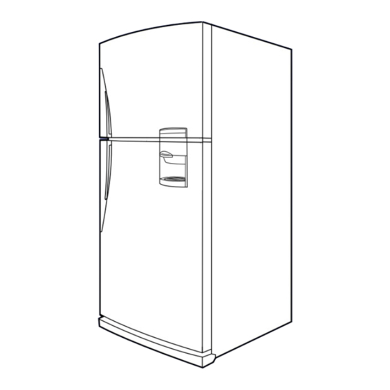
Samsung SR-606EV Service Manual
Hide thumbs
Also See for SR-606EV:
- Owner's instructions manual (36 pages) ,
- Owner's instructions manual (19 pages)
Table of Contents
Advertisement
S E R V I C E
R E F R I G E R A T O R
"A"
"A": WITH DISPENSER
S R - 6 0 8 E V
S R - 6 4 8 E V
S R - 6 8 8 E V
WITHOUT DISPENSER
SR-606EV
SR-646EV
SR-686EV
R E F R I G E R ATO R
Model : SR-608EV
SR-648EV
Model :
SR-688EV
M a n u a l
C O N T E N T S
3. Electrical Part Specifications & Standard
5. Outer Package Specification
7. Functions And Directions
10. Disassemble & Assemble Drawing And
11. Disassemble & Assemble Method
12. Packing Method
13. PCB Diagram
15. Main Components Specifacations
Advertisement
Table of Contents

Summarization of Contents
2. Product Specifications
3. Electrical part specifications & standard
Specifications for electrical components like compressors, evaporators, and refrigerants.
7. Function and Directions
7-1 The outer size
Provides dimensions (A, B, C, D) for different refrigerator models.
7-3 Freezing cycle
Diagram and description of the refrigerant flow in the freezing cycle.
7-4 PANEL display
Illustrates the refrigerator's control panel and display indicators.
7-5 Temperature control
Explains the temperature settings for freezer and refrigerator compartments.
7-6. Power freeze and Power
Details on the operation of power freeze and quick refrigeration functions.
7-7 Alarming
Describes various alarming sounds and their causes, like door open or forced operation.
7-8 Defrosting
Information on the automatic defrosting cycle and its timing.
7-9 Testing
Procedures for forced operation, forced defrosting, and test cancel mode.
7-10 Self diagnosis
Explains the self-diagnosis process initiated upon power-on.
7-11 Load status display
Details on how to access and interpret load status display modes.
11. Disassemble and assemble method
11-1 Refrigerator inside lamp replacement
Step-by-step guide for replacing the interior lamp in the refrigerator.
11-2 Freezer inside lamp replacement
Procedure for replacing the interior lamp in the freezer compartment.
11-3 Disassemble of refrigerator cooling part
Guide for removing shelves and cooling components from the refrigerator.
9. Failure diagnosis and repairment
Main PCB check
Procedure for checking the main PCB for issues and performing self-diagnosis.
9-1 No Input Power
Flowchart for diagnosing and resolving issues related to no power input.
9-2 Self diagnosis failure
Troubleshooting guide for failures detected during the self-diagnosis process.
1) Outer temperature sensor failure
Diagnosing and fixing issues with the outer temperature sensor.
2) R1, R2, refrigerator temp. sensor failure
Troubleshooting steps for refrigerator temperature sensor failures.
3) Refrigerator' s defrosting sensor failure
Diagnosing and resolving problems with the refrigerator's defrosting sensor.
4) F1, Freezer temp. sensor failure
Troubleshooting guide for the freezer's temperature sensor (F1).
5) Freezer' s defrosting sensor failure
Steps to diagnose and fix issues with the freezer's defrosting sensor.
9-3 In case of continuous alarming
Guidance for handling continuous alarming conditions and their causes.
1) In case of “Ding-Dong” alarming
Troubleshooting for 'Ding-Dong' alarm sounds, often related to door switches.
4) In case of the panel PCB key selection is impossible
Troubleshooting for when keys on the control panel are unresponsive.
9-4 In case of fan do not run
Diagnostic steps for when the refrigerator's fans fail to operate.
9-5 In case of swing fan in the refrigerator doesn' trun.
Troubleshooting guide for the refrigerator's swing fan not running.
1) In case of F-fan doesn't run
Steps to diagnose and fix issues with the freezer fan (F-fan).
2) In case of R-fan doesn' trun
Troubleshooting guide for when the refrigerator fan (R-fan) does not operate.
8. Circuit Operating Theory
8-1 Power supply part
Explanation of the refrigerator's power supply circuit operation.
8-3 Door S/W sensing part
Details on door switch sensing mechanisms and MICOM input.
8-4 “V” motor, location sensing part (Reed S/W)
Explains how the swing fan's location is sensed using a reed switch.
8-5. Temp. sensing part
Details on temperature sensing circuits using thermistors and MICOM inputs.
8-6 Comp and defrosting heater operating
Explains the operating logic of the compressor and defrosting heater.
10. Disassemble & assemble drawing and part list
10-1 Freezing Compartment
Exploded views and part numbers for the freezing compartment components.
10-2 Refrigerating Compartment
Diagrams and part lists for components within the refrigerating compartment.
10-3 Cabinet and Unit Compartment
Exploded views of the refrigerator's cabinet and internal unit compartments.
10-4 Door Parts
Diagrams illustrating the components of the refrigerator doors.
15. Main components specifications
1) REGULATOR
Specifications and features of 3-terminal positive voltage regulators.
2) REGULATOR(MC7812C)
Electrical characteristics and test conditions for the MC7812C voltage regulator.
MC 7805 AC(T)
Electrical characteristics and test conditions for the MC7805 AC(T) voltage regulator.
HIGH-VOLTAGE, HIGH-CURRENT SOURCE DRIVERS
Specifications for UDS2980 series high-voltage, high-current source drivers.
ELECTRICAL CHARACTERISTICS from -55°c to +125°c
Detailed electrical characteristics over a wide temperature range for source drivers.
KSR1005 NPN EPITAXIAL SILICON TRANSISTOR
Specifications for the KSR1005 NPN epitaxial silicon transistor.


Need help?
Do you have a question about the SR-606EV and is the answer not in the manual?
Questions and answers