Table of Contents
Advertisement
Quick Links
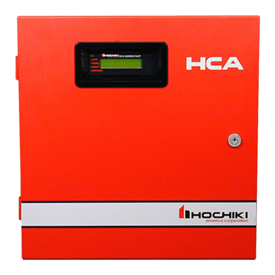
HCA Series
Conventional Fire Alarm System
(HCA-2, HCA-2D, HCA-4, HCA-4D, HCA-8, HCA-8D)
Installation and Operation Manual
Hochiki America Corporation
7051 Village Drive, Suite 100
Version 2.15
Buena Park, CA90621-2268
Created: 07/22/2013
714.522.2246 Corporate Headquarters
Updated: 06/30/2017
800.845.6692 Technical Support
HA-06-266
http://www.hochiki.com
Advertisement
Table of Contents

Related Manuals for Hochiki HCA-8


Summarization of Contents
Introduction
1.1 Product Features
Key features of the HCA panels, including zone count, DACT, NACs, and display.
1.2 Electrical Specifications
Detailed electrical parameters, power ratings, current limits, and component specifications.
1.3 Fire Alarm System Limitations
Explains general limitations of fire alarm systems and specific factors affecting smoke detector performance.
1.4 Installation Precautions
Critical warnings and safety guidelines for installing the HCA series control panel and associated equipment.
Controls and Indicators
2.1 Front Panel User Control Buttons
Describes the functions of the Acknowledge, Silence, and Reset buttons on the panel.
2.2 LED Indicators
Explains the status indications provided by the AC Power, Alarm, Trouble, and Silence LEDs.
2.3 Local Piezoelectric (PZT) Sounder
Details the distinct sounds the panel's internal sounder makes for alarm, trouble, and supervisory conditions.
Control Panel Installation
3.1 Agency Requirements
Lists the standards and listings applicable to the HCA series panel for fire alarm systems.
3.2 Requirements for All Installations
Outlines general installation requirements including wiring, compatible devices, and system checkout procedures.
3.3 Federal Communication Commission (FCC)
Covers FCC compliance rules and connection requirements for telephone lines.
3.4 Calculating Current Draw and Battery Size
Guides on determining system current draw and calculating appropriate battery backup requirements.
3.5 Mounting the Enclosure
Instructions for physically mounting the HCA control panel enclosure in the desired location.
3.6 AC Power Connection
Step-by-step guide for safely connecting the AC power supply to the control panel.
3.7 Battery Installation
Details the procedure for installing backup batteries into the HCA control panel enclosure.
3.8 Notification Appliance Circuit (NAC) Wiring
Explains how to wire notification appliance circuits (NACs) for various configurations, including Class B.
3.9 Zone Installation
Describes the wiring for conventional input zones, including Class B/C wiring and EOL resistors.
3.10 Inner Door Label (Wiring Diagram)
Provides a comprehensive wiring diagram of the HCA series panel, showing connections for inputs, outputs, and accessories.
3.11 Relay Outputs
Details the panel's 5 form C relays, including dedicated and programmable functions.
3.12 DACT Phone Lines
Explains the connection of telephone lines for the built-in Digital Alarm Communicator Transmitter (DACT).
3.13 Remote Annunciator (Model HCA-RA)
Covers the installation and connection of the optional HCA-RA remote annunciator.
3.14 Diagnostic LEDs
Explains the purpose and meaning of the various diagnostic LEDs on the HCA panel for troubleshooting.
Control Panel Operations
4.1 LCD Display Screens
Describes the various status screens displayed on the panel's LCD, including normal and off-normal conditions.
4.2 Operation Keys
Details the functions of the control panel's keypad keys for system operation and navigation.
4.3 Login Screen
Explains the process of accessing the panel via a password entry screen and default codes.
4.4 User Top Level Menu Options
Outlines the menu options available to a standard user for functions like fire drill and date/time setup.
4.5 Installer Top Level Menu Options
Presents the menu options accessible to installers, including programming and diagnostic functions.
4.6 Fire Drill
Instructions on how to initiate and stop a fire drill simulation from the panel.
4.7 Date/Time Setup
Guide for setting the panel's date, time, and daylight saving time parameters.
4.8 Walk Test
Procedure for performing on-site walk tests of zones and detectors to verify system functionality.
4.9 Event History
How to view and clear the panel's event history log, including event details and timestamps.
4.10 Disabling Circuits
Procedures for disabling/enabling zones and outputs, and performing manual DACT tests.
4.11 Manual DACT Test
Instructions for initiating a manual test of the Digital Alarm Communicator Transmitter (DACT).
4.12 Operating the Remote Annunciator
How to use a connected remote annunciator to view status and perform operations remotely.
Programming
5.1 Editing User and Installer Access Codes
How to change or set user and installer access codes for panel operation and programming.
5.2 Zone Programming Options
Configuration options for each zone, including type, response time, and NAC/relay activation.
5.3 Notification Appliance Circuit (NAC) and Relay Programming
Programming for NACs, relays, strobe synchronization, and auxiliary power functions.
5.4 Releasing Programming Options
Configuration for water and agent releasing functions, including cross-zoning, delays, and disconnect switch integration.
5.5 Remote Annunciator
Settings to enable or disable the remote annunciator and configure its presence.
5.6 DACT Setup
Configuration for the built-in DACT, including auto test, reporting delays, account details, and phone lines.
5.7 Panel Factory Default Setup
How to restore the panel to its original factory default programming settings.
DACT Reporting Codes and Compatible Receivers
6.1 DACT Reporting Codes for SIA and Contact ID
Lists specific event codes used for SIA and Contact ID reporting formats by the DACT.
Compatible Devices for the HCA Series Panel
7.1 Compatible Conventional Initiating Devices
Lists compatible smoke detectors, heat detectors, and pull stations for the HCA panel.
7.2 Compatible Releasing Devices
Lists compatible actuators, solenoids, abort switches, and EOL modules for releasing applications.
7.3 Compatible Heat Detector Cable
Details compatible heat detector cables and their maximum allowable lengths.
7.4 Compatible Notification Appliances
Lists compatible Gentex notification appliances (speaker strobes, horns) for synchronized applications.
Need help?
Do you have a question about the HCA-8 and is the answer not in the manual?
Questions and answers