Table of Contents
Advertisement
MAINTENANCE MANUAL
The manuals for maintenance are comprised of the following
three manuals including this manual:
MAINTENANCE MANUAL, MAINTENANCE INFORMATION,
and INSTALLATION MANUAL.
MSC-500
MSG-500
MSX-500
MSX-500III MSD-515
MSC-501
MSD-501
MSD-501II MSD-516II MSG-805
MSG-501
MSX-501
MSX-501III MSD-518II MSG-806
MSG-502
MSX-502
MSX-502III MSC-701
Before starting operation, maintenance, or programming, carefully read the
manuals supplied by Mori Seiki, the NC unit manufacturer, and equipment
manufacturers so that you fully understand the information they contain.
Keep the manuals carefully so that they will not be lost.
Applicable Model
NC LATHES
Applicable NC Unit
MSX-511
MSX-511III MSC-802
MSC-515
MSC-516
MSD-516
MSC-518
MSD-518
MSC-521
MSC-700
MSC-801
MSC-803
MSG-803
MSX-803
MSX-803III
MSX-805
MSX-805III
SEICOS Σ21L
MM-CENL-H2EN
Advertisement
Table of Contents

Related Manuals for mori seiki MSC-803


Summary of Contents for mori seiki MSC-803
- Page 1 MSX-502III MSC-701 Before starting operation, maintenance, or programming, carefully read the manuals supplied by Mori Seiki, the NC unit manufacturer, and equipment manufacturers so that you fully understand the information they contain. Keep the manuals carefully so that they will not be lost.
- Page 2 • All rights reserved: reproduction of this instruction manual in any form, in whole or in part, is not permitted without the written consent of Mori Seiki. The product shipped to you (the machine and accessory equipment) has been manufactured in accordance with the laws and standards that prevail in the relevant country or region.
- Page 3 CONTENTS SIGNAL WORD DEFINITION FOREWORD DAILY INSPECTION REGULAR INSPECTION OUTLINE OF SYSTEMS INDEX HOW TO ORDER THE MACHINE PARTS...
- Page 4 SIGNAL WORD DEFINITION A variety of symbols are used to indicate different types of warning information and advice. Learn the meanings of these symbols and carefully read the explanation to ensure safe operation while using this manual. <Symbols related with warning> The warning information is classified into three categories, DANGER, WARNING, and CAUTION.
- Page 5 Use of the NC lathe under criteria other than those stated above is considered inappropriate. Mori Seiki is not responsible for any danger or damage arising from improper operation of the machine. Some examples of improper machine usage are indicated below.
- Page 6 CHAPTER A DAILY INSPECTION...
- Page 7 CONTENTS DAILY INSPECTION THE IMPORTANCE OF DAILY INSPECTION ......A-1 NOTES ON INSPECTIONS AND MAINTENANCE ......A-2 Work in General .
-
Page 8: The Importance Of Daily Inspection
If an abnormality is discovered during daily inspection, it must be reported to the supervisor and the person responsible for machine maintenance. Quick action should be taken. If a problem that cannot be remedied by the user or whose cause cannot be determined occurs, contact Mori Seiki and the equipment manufacturers. -
Page 9: Notes On Inspections And Maintenance
DAILY INSPECTION NOTES ON INSPECTIONS AND MAINTENANCE Pay adequate consideration to safety and hygiene when performing work such as machine inspections, setup, and cleaning, and implement appropriate safety and hygiene measures. Some points that require attention are cited below but note that other necessary measures must also be taken and the necessary training given to ensure the safety of the operator, before (s)he uses the machine. -
Page 10: Work Inside The Machine
DAILY INSPECTION Work Inside the Machine WARNING (1) Confirm that the main power supply to the machine is shut off before entering the machine to do work inside it. Be aware that if you close the machine door after entering the machine, it may not be possible to open the door from the inside. -
Page 11: Lubricating And Hydraulic Oil
(2) Never remove the filter from the filter port of each tank when supplying oil. If oils other than those specified by Mori Seiki are used mistakenly or different brands CAUTION of oil are mixed, clean the tank and flush piping immediately. -
Page 12: Supplying Oil In Daily Maintenance
DAILY INSPECTION SUPPLYING OIL IN DAILY MAINTENANCE Supplying Oil to the Lubricating Oil Tank If the oil level in the lubricating oil tank drops, an alarm indication is given. If this low lubricating oil level alarm is given, supply lubricating oil. <Procedure>... -
Page 13: Greasing The Chuck Master Jaws
DAILY INSPECTION Greasing the Chuck Master Jaws If the master jaws are not lubricated properly with grease, the gripping force of the chuck will be reduced. If the spindle is rotated while the master jaws are not properly greased, the workpiece will fly out of the chuck, causing injuries and machine damage. -
Page 14: Inspection Of The Chuck
DAILY INSPECTION INSPECTION OF THE CHUCK <Daily oiling> To maintain high chuck accuracy over a prolonged period, it is necessary to supply lubricating oil. Improper lubrication will cause the following problems. • Faulty operation at low hydraulic pressure • Insufficient gripping force •... -
Page 15: Cleaning Machining Chamber/Setup Station
DAILY INSPECTION CLEANING MACHINING CHAMBER/SETUP STATION To maintain machining accuracy for the optimum length of time, always clean the machining chamber and setup station daily following completion of machine operations. DANGER When inspecting and cleaning the machining chamber and setup station, turn OFF the main power and disconnect the plant-side power supply (breaker). -
Page 16: Cleaning The Front Cover Of The Tailstock (With Built-In Tailstock Spindle)
DAILY INSPECTION Cleaning the Front Cover of the Tailstock (with Built-in Tailstock Spindle) Dust and foreign matter will accumulate in the coolant holes on the front cover of the tailstock allowing coolant to enter the bearings. This will cause the bearings to seize. Clean the coolant holes in the front cover of the tailstock at least once a week. -
Page 17: Cleaning The Rear Of The Cylinder (Hollow Chuck)
A-10 DAILY INSPECTION Cleaning the Rear of the Cylinder (Hollow Chuck) Coolant and chips flow to coolant pan at the rear of the cylinder via the through hole in the draw pipe. The coolant returns to the coolant tank via the drain hose. Chips accumulate on the punched-metal sheet at the rear of the cylinder. -
Page 18: Cleaning The Drain Oil Receiver For The Lubricating Oil
DAILY INSPECTION A-11 CLEANING THE DRAIN OIL RECEIVER FOR THE LUBRICATING OIL If the drain oil receiver for the lubricating oil is at the rear or the side of the machine, dispose of the waste oil before the drain oil receiver becomes full. The drain oil receiver is provided to prevent lubricating oil being mixed into the coolant. -
Page 19: Cleaning Radiator
A-12 DAILY INSPECTION CLEANING RADIATOR If the radiator on the hydraulic tank is clogged, the oil temperature rises resulting in unit failure. Clean the radiator at regular intervals. <Cleaning interval> As required <Necessary tools> • Air gun Radiator <Procedure> 1) Turn OFF the main power. 2) Remove dust adhering to the radiator with a compressed air gun. -
Page 20: Precautions When Using Chip Conveyor
DAILY INSPECTION A-13 PRECAUTIONS WHEN USING CHIP CONVEYOR WARNING (1) Do not operate the chip conveyor or perform maintenance and inspection tasks without reading and obtaining a thorough understanding of the contents of the chip conveyor instruction manual "COOLANT FILTER MANUAL" published separately. (2) Keep the chip conveyor instruction manual "COOLANT FILTER MANUAL"... -
Page 21: Cleaning Chip Conveyor
A-14 DAILY INSPECTION Cleaning Chip Conveyor <Cleaning interval> Once or twice daily. <Necessary tools> • Rags <Procedure> 1) Press the CHIP CONVEYOR [FOR] button on the CHIP CONVEYOR operation panel. The [FOR] button is illuminated. STOP BACK The chip conveyor moves forward to discharge chips from machine. -
Page 22: Opening/Closing The Electrical Cabinet Door
DAILY INSPECTION A-15 OPENING/CLOSING THE ELECTRICAL CABINET DOOR DANGER Before attempting maintenance and inspection inside the electrical cabinet, be sure to turn OFF the plant-side power supply (circuit breaker). Even when the main power switch on the electrical cabinet is turned OFF, parts of the cabinet may still hold residual current and give an electric shock if accidentally touched. -
Page 23: Closing The Electrical Cabinet Door
A-16 DAILY INSPECTION 5) Open the electrical cabinet door. 10.2 Closing the Electrical Cabinet Door 1) Close the left side of the electrical cabinet door. 2) Close the right side of the electrical cabinet door. 3) Rotate the lever downward. 4) Push the lever inward. -
Page 24: Main Power Switch
DAILY INSPECTION A-17 10.3 Main Power Switch WARNING When the main power switch is locked, maintenance procedures are performed. Do not place the main power switch in the [ON] position. When electrical over-current occurs in the machine, the breaker is actuated, the power supply is automatically turned OFF, and the main power switch automatically moves to the [TRIP] setting. - Page 25 A-18 DAILY INSPECTION Type C 1) Place the main power switch in the [OFF] position. 2) While pushing the shutter plates in the direction of arrows, attach a padlock. Shutter plate Type D 1) Place the main power switch in the [OFF] position. 2) Put a driver into the release screw.
-
Page 26: Prolonged Idle Period
DAILY INSPECTION A-19 PREPARATION FOR MACHINE OPERATION AFTER PROLONGED IDLE PERIOD Perform the following operations in the order specified after the machine has been idle for a prolonged period of time (1) Forced lubrication of ball screws and spindle bearings. (2) Full stroke travel of all axes. - Page 27 CHAPTER B REGULAR INSPECTION...
- Page 28 CONTENTS REGULAR INSPECTION IMPORTANCE OF INSPECTIONS ........B-1 CHECKS PRIOR TO MAINTENANCE .
- Page 29 14.2 Replacing the Servo Absolute Position Sensing Battery ....B-30 14.2.1 Type 1 (Alkaline Battery/Manganese Battery)....B-30 14.2.2 Type 1 (Lithium Battery) .
- Page 30 (3) For queries or concerns related to the contents of the instruction manuals, circuit diagrams, and ladder diagrams, contact Mori Seiki Service Department for assistance. (4) If the cause of a problem cannot be determined or remedied, contact Mori Seiki Service Department and/or parts manufacturers for assistance.
- Page 31 (4) Provide clear warning that the machine is being maintained and operations cannot be performed. WARNING (1) Ensure only parts specified by Mori Seiki are used during parts replacement. Mori Seiki does not accept responsibility for problems arising from the use of non-specified parts. Use of non-specified...
- Page 32 (2) The parameters are set on shipment in accordance with the machine specifications; do not change them without first consulting Mori Seiki. If the parameters are changed without consultation, the machine may operate in an unexpected manner, causing accidents involving serious injuries or damage to the machine.
- Page 33 (5) When changing parts, be sure to use genuine parts specified by Mori Seiki. Mori Seiki cannot accept responsibility for any trouble arising from the use of parts not specified by Mori Seiki. Using parts that are not specified will not only impair the performance of the machine; it will also make the machine unsafe and could lead to serious injuries or damage to the machine.
- Page 34 REGULAR INSPECTION CLEANING THE ELECTRICAL CABINET AIR FILTER The electrical cabinet is not cooled directly by outside air; it is cooled indirectly through heat exchange between outside air, taken into the cabinet through the duct, and inside air. Therefore, if the air filter at the air suction port is clogged, the inside of the electrical cabinet will not be cooled satisfactorily.
- Page 35 REGULAR INSPECTION CLEANING THE COOLANT TANK If fine chips and other foreign matter accumulate in the coolant tank, the specified coolant supply cannot be maintained and coolant supply to the cutting point is insufficient. In addition, if contaminated coolant is pumped from the coolant tank, the service life of the pump is reduced.
- Page 36 REGULAR INSPECTION CLEANING THE LUBRICATING OIL TANK Lubricating Unit Tank/Suction Filter/Fill Port Filter Cleaning <Cleaning interval> Tank: Every 1000 hours of operation. Suction filter/fill port filter: Every 500 hours of operation. <Necessary tools> • Screwdriver • Neutral detergent/kerosene (for cleaning) <Procedure>...
- Page 37 REGULAR INSPECTION 13) Press the manual lubrication button for more than 10 seconds to supply lubricant to the slideways. 14) Make sure that lubricating oil is supplied to the slideway surfaces. Inspection Items for the Lubricating Oil Tank Periodic inspection items for the lubricating oil tank are indicated below. By referring to the inspection items, carry out inspection and maintenance work at the specified inspection intervals.
- Page 38 (piping or Air bleeding from the piping piping distributor malfunction) Distributor malfunction Replacement Following air bleeding from the piping, ensure that the pressure rises to between NOTE 1.0 MPa - 1.2 MPa. Contact Mori Seiki Service Department for assistance.
- Page 39 B-10 REGULAR INSPECTION Line filter piping Line filter discharge outlet (plug insertion point) Manual lubrication button Relief valve Suction filter...
- Page 40 • Press the manual lubrication button. • Set the pump discharge pressure to 1.2 MPa using the relief valve adjusting screw. If unable to set the pressure to 1.2 MPa, the pump is malfunctioning. Contact Mori Seiki NOTE Service Department for assistance.
- Page 41 B-12 REGULAR INSPECTION CLEANING THE SUCTION STRAINER IN THE HYDRAULIC OIL TANK If the suction strainer becomes clogged, pumps and piping may be damaged, resulting in hydraulic unit failure. Clean the suction strainer at regular intervals. <Cleaning interval> Every 1000 hours of operation. <Necessary tools>...
- Page 42 REGULAR INSPECTION B-13 6) Clean the suction strainer using the following procedure: a) Remove the suction strainer. Clamp the suction pipe with a pipe wrench and turn the suction strainer to the left with a CAUTION monkey wrench. If the suction strainer is turned without clamping the suction pipe, the suction pipe will turn with it, causing an oil leak.
- Page 43 B-14 REGULAR INSPECTION CLEANING THE FANS <Battery position> • Electrical cabinet • Machine side cover • Hydraulic pump <Cleaning interval> Every 1000 hours of operation <Procedure> 1) Turn off the power. 2) Remove the fan cover. 3) Blow the fan with compressed air. The temperature inside the cabinet must be lower than 45°C;...
- Page 44 REGULAR INSPECTION B-15 CLEANING INSIDE THE ELECTRICAL CABINET Although the electrical cabinet is constructed to shut off external air, foreign matter such as dust and dirt may enter the cabinet through the gap or when the door is opened. Accumulation of foreign matter on the printed circuit boards or other electronic components could cause machine malfunction.
- Page 45 B-16 REGULAR INSPECTION REPLACING THE MACHINING CHAMBER OBSERVATION WINDOW The machining chamber observation window consists of polycarbonate and tempered glass. Polycarbonate effectively resists strong impact. Tempered glass prevents the window becoming opaque due to repeated cutting chip impacts. The machining chamber observation window is a consumable part.
- Page 46 B-17 (1) When replacing the machining chamber observation window, contact Mori Seiki NOTE Service Department and use a window of the specified type. Mori Seiki does not accept responsibility for problems arising from the use of a non-specified window type.
- Page 47 B-18 REGULAR INSPECTION INSPECTION AND REPLACEMENT OF SLIDE SEALS Slide seals are used on each slideway. The slide seals are used to prevent the entry of chips beyond them and to maintain an oil film of uniform thickness. Check the slide seals periodically. Pay careful attention to abnormal wear on the lip or scratches or damage due to chips.
- Page 48 If the same timing belt is used without replacement, the axis could drop due to damage and wear of the belt, causing damage to the machine. Contact the Mori Seiki Service Department for assistance when replacing timing belts. NOTE <Replacement Interval>...
- Page 49 B-20 REGULAR INSPECTION CHANGING FLUID OF HYDRAULIC TANK Change the hydraulic fluid in the hydraulic unit tank at regular intervals while paying attention to the following considerations. (1) Maintain the oil level of hydraulic fluid in the tank at the correct level; make sure CAUTION that the pump unit does not suck in air.
- Page 50 REGULAR INSPECTION B-21 8) Replace the fill port cap. Turn ON the main power. 10) Confirm pump pressure and suction noise are normal. If the suction noise is louder than prior to oil replacement, check the oil level again. NOTE...
- Page 51 For MSC-801, refer to the MAINTENANCE INFORMATION published separately. <Battery to be used> Absolute Position Sensing Type NC Unit Memory Back-up Battery Battery MSC-515 MSD-515 MSC-500 MSC-501 MSD-501 MSD-501II MSG-500 MSG-501 MSC-516 MSD-516 Alkaline battery/Manganese battery × 4 pcs.
- Page 52 REGULAR INSPECTION B-23 Absolute Position Sensing Type NC Unit Memory Back-up Battery Battery • Electrical cabinet side Battery unit × 1 set E30027 [ER6 BKO-NC2157H01] MSC-803 • Operation panel side Battery unit × 1 set Type 2 Battery unit × 1 set E30028 [ER6-B4D-01] E03031 [ER3V] MSG-803...
- Page 53 To avoid the danger of lost data, you is recommended to save the memory data to an external I/O device or a memory card. Mori Seiki can accept no responsibility if data in the memory such as parameters and programs is lost.
- Page 54 To avoid the danger of lost data, you are recommended to save the memory data to an external I/O device. Mori Seiki does not have any responsibility for the loss of memory data. <Battery position> The batteries are installed in the electrical cabinet door.
- Page 55 To avoid the danger of lost data, you are recommended to save the memory data to an external I/O device. Mori Seiki does not have any responsibility for the loss of memory data. <Battery position> The battery unit is installed inside the operation panel.
- Page 56 REGULAR INSPECTION B-27 <Procedure> 1) Turn on the power. 2) Press the NC power switch (on). 3) Press the NC power switch (off). 4) Turn off the power. 5) Open the operation panel door. 6) Remove the connector attached to the battery. Do not pull the battery cable.
- Page 57 To avoid the danger of lost data, you is recommended to save the memory data to an external I/O device or a memory card. Mori Seiki can accept no responsibility if data in the memory such as parameters and programs is lost.
- Page 58 To avoid the danger of lost data, you is recommended to save the memory data to an external I/O device or a memory card. Mori Seiki can accept no responsibility if data in the memory such as parameters and programs is lost.
- Page 59 B-30 REGULAR INSPECTION 14.2 Replacing the Servo Absolute Position Sensing Battery Change the Absolute Position Sensing Batteries by following the procedure indicated below. The type and mounting position of the Absolute Position Sensing Batteries vary depending NOTE on the machine. 14.2.1 Type 1 (Alkaline Battery/Manganese Battery) Change the batteries while power is being supplied to the NC.
- Page 60 REGULAR INSPECTION B-31 14.2.2 Type 1 (Lithium Battery) WARNING Since the battery is located in the electrical cabinet, carry out battery change very carefully. If you touch live parts by mistake, you could sustain an electric shock. Change the batteries while power is being supplied to the NC. If the batteries are CAUTION changed with the NC power supply shut off, the absolute position data in the memory will be lost.
- Page 61 B-32 REGULAR INSPECTION 10) Mount the battery case. 11) Press the NC power switch (off). 12) Turn off the power. 13) Close the electrical cabinet door. Refer to Chapter A 10. "OPENING/CLOSING THE ELECTRICAL CABINET DOOR". 14) Place the electrical cabinet door interlock key-switch in the ON position.
- Page 62 REGULAR INSPECTION B-33 14.2.3 Type 2 Change the battery with the power supply shut off. CAUTION Be sure to change the battery in less than 30 minutes. The absolute position data in the memory will be lost if the power supply is shut off for 30 minutes or more.
- Page 63 B-34 REGULAR INSPECTION 6) Unplug the cable connector. 7) Mount a new printed circuit board.
- Page 64 REGULAR INSPECTION B-35 14.2.4 Type 3 (2CR5 Type Lithium Photo Battery) Change the batteries while power is being supplied to the NC. CAUTION If the batteries are changed with the NC power supply shut off, the absolute position data in the memory will be lost. <Battery position>...
- Page 65 B-36 REGULAR INSPECTION 14.2.5 Type 4 WARNING Since the battery is located in the electrical cabinet, carry out battery change very carefully. If you touch live parts by mistake, you could sustain an electric shock. Change the batteries while power is being supplied to the NC. If the batteries are CAUTION changed with the NC power supply shut off, the absolute position data in the memory will be lost.
- Page 66 REGULAR INSPECTION B-37 10) Mount the battery case. 11) Press the NC power switch (off). 12) Turn off the power. 13) Close the electrical cabinet door. Refer to Chapter A 10. "OPENING/CLOSING THE ELECTRICAL CABINET DOOR". 14) Place the electrical cabinet door interlock key-switch in the ON position.
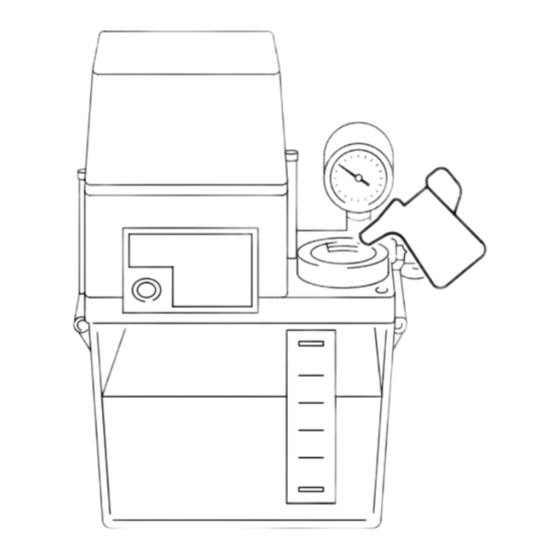
- Page 67 B-38 REGULAR INSPECTION ADJUSTING THE SETTING PRESSURE WARNING Operating the machine while the pressure gages (hydraulic and air) do not indicate the correct values could lead to serious injuries and damage to the machine. If the gages do not indicate the correct values, adjust them by following the procedure below.
- Page 68 REGULAR INSPECTION B-39 15.2 Adjusting Air Pressure After the installation of the machine, adjust the main air pressure. The main air pressure can be adjusted with the regulator mounted at the air control unit panel. The shape of the regulator may differ depending on the machine model. NOTE <Procedure>...
- Page 69 B-40 REGULAR INSPECTION ADJUSTING THE OIL SKIMMER SEPARATION TANK DRAIN (OPTION) If oil is not being removed from the separation tank or coolant is being removed with the waste oil into the oil pan, adjust the height of the drain adjustment nut according to the following procedure. <Adjustment interval >...
- Page 70 CHAPTER C OUTLINE OF SYSTEMS...
- Page 71 CONTENTS OUTLINE OF SYSTEMS SLIDEWAY (FEED AXIS) LUBRICATION SYSTEM ......C-1 HYDRAULIC SYSTEM..........C-1 COOLANT SYSTEM .
-
Page 72: Coolant System
OUTLINE OF SYSTEMS SLIDEWAY (FEED AXIS) LUBRICATION SYSTEM The lubrication system is used to form oil films on the slideways (ball guides) to ensure smooth motion of the saddle and cross slide and prevent wear on the slideways (ball guides). The lubrication system consists of a pump unit, distributors, and piping parts. - Page 73 OUTLINE OF SYSTEMS CHUCK AND CYLINDER SYSTEM The chuck and cylinder system consists of the following elements: • Hydraulic unit • Solenoid valve • Hydraulic cylinder • Draw bar (pipe) • Chuck • Other accessories The chuck is mounted on the spindle nose and the hydraulic cylinder at the rear end of the spindle.
- Page 74 (2) If you use a workpiece holding fixture other than the chuck supplied with the machine, be sure to contact Mori Seiki to prevent accidents. Mori Seiki is not responsible for accidents caused by the use of fixtures prepared by the customer without consulting Mori Seiki.
- Page 75 If it is necessary to mount a chuck or fixture in the chuck or a fixture which is directly mounted to the spindle in order to hold a workpiece, contact Mori Seiki or the chuck manufacturer for the measures that should be taken.
- Page 76 OUTLINE OF SYSTEMS Maximum Allowable Chuck Speed The maximum allowable speed is the spindle speed at which the gripping force is 1/3 less than the gripping force obtained when the spindle is not rotating. The maximum allowable spindle speed is determined under the following conditions: <Conditions>...
- Page 77 OUTLINE OF SYSTEMS Relationship between Gripping Force and Spindle Speed WARNING The chuck gripping force is reduced as spindle speed increases, generating centrifugal force on jaws. Heavy cutting at high spindle speeds might cause the workpiece to slip in the chuck or fly out of the chuck. The curves in this diagram show how gripping force is reduced as spindle speed increases when standard soft jaws are used.
- Page 78 OUTLINE OF SYSTEMS Relationship between Jaw Height and Allowable Cylinder Thrust (1) Do not use the chuck at a force exceeding the allowable cylinder thrust. If you do, the service life of the chuck will be shortened and accidents will occur due to fatigue of component parts. (2) If high jaws are used, use the chuck at a lower cylinder thrust.
- Page 79 OUTLINE OF SYSTEMS Relationship between Cylinder Thrust and Gripping Force To determine the cutting conditions, use the following chart (Cylinder Thrust - gripping force diagram) for reference. Note that the relationship will vary slightly according to the grease characteristics. Example) Kitagawa hollow chuck 147.1 B-212 98.0...
- Page 80 OUTLINE OF SYSTEMS Setting the Chucking Pressure The chucking pressure can be increased up to the main pressure of the hydraulic system. However, the chucking pressure value should be smaller than the maximum pressure allowed for the chuck or the cylinder, whichever is lower. WARNING If a force exceeding the allowable cylinder thrust is applied to the chuck, the components or bolts of the chuck will be damaged and chuck gripping...
- Page 81 C-10 OUTLINE OF SYSTEMS PNEUMATIC SYSTEM The pneumatic system consists of the air filter, regulator, air solenoid valve, and piping. 1) The compressed air supplied to the air supply port has moisture and dust removed from it by the air filter, generating clean, dry air. 2) Next, the air pressure is adjusted to the appropriate pressure for the pneumatic devices by the regulator.
- Page 82 INDEX INDEX Page Adjusting Air Pressure ............B-39 Adjusting Hydraulic Unit Main Pressure .
- Page 83 INDEX IMPORTANCE OF INSPECTIONS ..........B-1 INSPECTION AND REPLACEMENT OF SLIDE SEALS .
- Page 84 INDEX Safety Practices when Mounting/Removing a Chuck ....... C-3 Setting the Chucking Pressure ..........C-9 SLIDEWAY (FEED AXIS) LUBRICATION SYSTEM.
- Page 85 HOW TO ORDER THE MACHINE PARTS To order the parts used in your machine, inform your name and the following items to the representative from which you purchased. (1) MACHINE MODEL (2) SERIAL No. (3) ORDER No. (4) QUANTITY (5) PART NAME (6) Page number (7) Number of revisions Inform the items (5), (6), and (7) only when available.
- Page 86 <Example> Ordering the limit switch for checking the tailstock clamp/unclamp in the SL-25A/500 (1) Check the MACHINE MODEL and SERIAL No. on ELECTRICAL RATING the ELECTRICAL RATING plate attached to the MACHINE MODEL : 25A5 electrical cabinet. SERIAL NO. 2501 MACHINE MODEL: SL-25A/500 PHASE SERIAL No.:...
- Page 87 Comments can also be submitted using the company website at http://www.moriseiki.com. Name of Manual MAINTENANCE MANUAL Number of Revisions MM-CENL-H2EN (2007.8) Name Company Department Telephone Address Chapter Page Line Comments/Requests For Mori Seiki's Use - Do not write below this line. Description Reception No. Received by...
- Page 88 For these values, refer to the values specified in the machine specification table. If the required value is not found in the table, contact Mori Seiki. Units and numerical values in ( ) in the SI column indicate the formal expression of the SI NOTE unit system.
- Page 89 Charlotte, San Francisco Head Office & Technical Center Unit 02, 8/F., Vicwood Plaza, 199 Des Voeux Road, Central, Hong Kong MORI SEIKI MEXICO, S.A. DE C.V. Phone: (852)-2757-8910 Fax.: (852)-2757-7839 Head Office & Technical Center MORI SEIKI (SHANGHAI) CO., LTD.
Need help?
Do you have a question about the MSC-803 and is the answer not in the manual?
Questions and answers