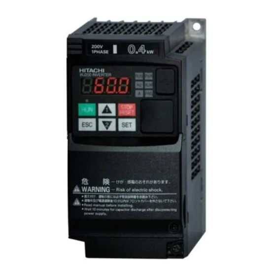
Table of Contents

Summarization of Contents
Industry-leading Levels of Performance
High starting torque of 200% or greater
Achieved by sensorless vector control for heavy-duty applications.
Speed regulation at low-speed is greatly improved
Fluctuation reduced by half compared to the previous model.
Trip avoidance functions
Functions reduce nuisance tripping and protect equipment.
Simple positioning control
Selectable speed or positioning control with feedback signal.
Induction motor & Permanent magnetic motor control
Drives both IM and PM motors; energy saving and miniaturization with PM.
Global standards
Conformity to global standards
CE, UL, c-UL, c-Tick approvals for compliance.
Sink/source logic is standard
Logic input/output terminals configurable for sink or source logic.
Wide input power voltage range
Input voltage 240V for 200V class and 480V for 400V class.
Pursuit of Ease of Use
Easy sequence [EzSQ] programming function
Program creation and simplification via EzSQ software for cost savings.
Safe stop function
Hardware-based shutdown for reliable safe stop, meeting safety standards.
Password function
Prevents parameter changes or hides parameters for security.
Network compatibility & External ports
Standard RS-485, USB, RS-422 ports; optional expansion cards.
Ease of wiring
Screw-less terminals for control circuit wiring for simplified connections.
Easy to maintain
Features like data comparison, quick display, and user-changed parameter display.
Ease of Maintenance
Long life time components
Design life of 10 years or more for DC bus capacitors and cooling fan.
Life time warning function
Diagnoses lifetime of DC bus capacitors and cooling fan(s).
Easy-removable cooling fan
Cooling fan replaceable without special tools for convenience.
Environmental Friendliness
Micro surge voltage suppress function
Hitachi original PWM control limits motor terminal voltage.
EU RoHS compliant
Environment-friendly inverter meeting RoHS requirements.
Varnish coating of internal PC board
Standard feature for enhanced environmental protection.
Various Versatile Functions
Dual rating
Supports both heavy and normal duty with one frame size smaller for applications.
Watt-hour monitor
Displays energy consumption in kWh for monitoring.
Improvement of environment
Features like varnish coating and two monitor output terminals.
Built-in BRD circuit
Built-in braking resistor circuit for all models, with optional resistor.
EZCOM (Peer-to-Peer communication)
Supports peer-to-peer communication between multiple inverters.
Flexible display functions
Automatic return to initial display and display limitation features.
Standard Specifications
1-phase 200V class
Detailed specifications for 1-phase 200V class models.
3-phase 200V class
Detailed specifications for 3-phase 200V class models.
3-phase 400V class
Detailed specifications for 3-phase 400V class models.
Operation and Programming
Operation Panel
Overview of the digital operator controls and indicators.
Keypad Navigation Map
Illustrates navigation through function groups and parameters.
Single-Digit Edit Mode
Method for quick parameter adjustment using digit-by-digit navigation.
Terminal (Arrangements/Functions)
Terminal Description
Lists and describes various terminal symbols and their names.
Terminal Arrangement and Screw Diameter
Shows terminal layout and screw diameter for different models.
Terminal Arrangement of Control Circuit Terminals
Diagram of control circuit terminal connections.
Wiring sample of control logic terminal (Sink logic)
Example wiring for control logic using sink logic.
Sink/source logic of intelligent input terminals
Explains sink/source logic configuration for input terminals.
Hardware Switches
Termination resistor selection switch
Switch for activating the built-in termination resistor.
Safe stop function selection switch
Switch to enable or disable the safe stop function.
EDM function selection switch
Switch to enable or disable the EDM function.
Connecting Diagram
Source Type Logic
Wiring diagram illustrating source type logic connections.
Sink Type Logic
Wiring diagram illustrating sink type logic connections.
Connecting to PLC
Connection with Input Terminals
Diagrams for connecting PLC inputs using internal or external power.
Connection with Output Terminals
Diagrams for connecting PLC outputs to the inverter.
Attention when inverter plurals is used
Guidance on preventing unwanted current flow with multiple inverters.
For Correct Operation
Precaution for Correct Usage
Guidelines for safe and proper use of the inverter.
Application to Motors
Guidance on selecting and applying motors with the inverter.
Notes on Use
Important usage notes covering drive and installation environment.
[Main power supply]
Information on AC reactor installation and private power generator use.
Notes on Peripheral Equipment Selection
Guidance on selecting peripheral equipment like contactors and relays.
High-frequency Noise and Leakage Current
How inverter operation affects noise and leakage current.
Lifetime of Primary Parts
Information on the expected lifespan and replacement of key components.


Need help?
Do you have a question about the WJ200-007HF and is the answer not in the manual?
Questions and answers