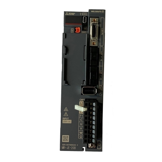
Summarization of Contents
Safety Instructions
WARNING and CAUTION Definitions
Explains the meaning of WARNING and CAUTION safety levels used in the manual for hazard communication.
Safety Symbols Explanation
Describes the meaning of diagrammatic symbols used for safety instructions, indicating what must not be done and what must be done.
1. FUNCTIONS AND CONFIGURATION
1.1 Summary
Provides an overview of the MELSERVO-JE series servo amplifier features, capabilities, and communication methods.
2. INSTALLATION
2.1 Installation Direction and Clearances
Details required installation directions and minimum clearances for proper servo amplifier operation and heat dissipation.
3. SIGNALS AND WIRING
3.1 Input Power Supply Circuit
Explains the necessary wiring for the servo amplifier's input power supply circuit, including circuit protection.
3.3 Explanation of Power Supply System
3.3.1 Signal Explanations
Details the function and connection destination for various power supply signals, terminals, and regenerative options.
3.5 Signal (Device) Explanations
3.5.1 Input Device
Lists and explains input device pins and parameters for setting devices on the servo amplifier's connectors.
3.7 Alarm Occurrence Timing Chart
3.7.1 When You Use the Forced Stop Deceleration Function
Illustrates the timing chart for alarm occurrence when the forced stop deceleration function is enabled.
3.8 Interfaces
3.8.1 Internal Connection Diagram
Shows the internal connection diagram for servo amplifier interfaces, including I/O and communication ports.
3.10 Servo Motor with an Electromagnetic Brake
3.10.1 Safety Precautions
Provides essential safety precautions for handling servo motors with electromagnetic brakes and their circuits.
4. STARTUP
4.1 Switching Power On for the First Time
Guides the user through the initial power-on procedure and startup checks for the servo amplifier.
4.3 Switch Setting and Display of the Servo Amplifier
4.3.1 Axis Selection Rotary Switch (SW1)
Explains how to set the control axis number using the rotary switch on the servo amplifier.
5. PARAMETERS
5.1 Parameter List
Lists all available parameters for the servo amplifier, categorized for easy reference and modification.
5.2 Detailed List of Parameters
5.2.1 Basic Setting Parameters ([Pr. PA_ _ ])
Provides detailed explanations for basic setting parameters, including initial values, units, and setting ranges.
6. NORMAL GAIN ADJUSTMENT
6.1 Different Adjustment Methods
Outlines various methods for adjusting servo amplifier gains, including auto tuning and manual modes.
6.3 Auto Tuning
6.3.1 Auto Tuning Mode
Explains the auto tuning function, which estimates machine characteristics to set optimum gains automatically.
7. SPECIAL ADJUSTMENT FUNCTIONS
7.1 Filter Setting
Describes various filters available for suppressing mechanical vibration and improving system response.
7.3 Tough Drive Function
7.3.1 Vibration Tough Drive Function
Details the function for preventing vibration by resetting filters instantaneously based on detected machine resonance.
11.5.2 MR-BAT6V1SET-A Battery
(1) Parts Identification and Dimensions
Shows the identification and dimensional drawings of the MR-BAT6V1SET-A battery pack.
11.10 Noise Reduction Techniques
(1) Noise Reduction Techniques
Provides general techniques and specific measures to reduce noise affecting the servo amplifier and peripheral equipment.
12. ABSOLUTE POSITION DETECTION SYSTEM
12.1 Summary
Introduces the absolute position detection system and its key features for maintaining position data.
App. 2 Handling of AC Servo Amplifier Batteries for the United Nations Recommendations on the Transport of Dangerous Goods
(1) Target Model
Lists target models for battery handling and their specifications regarding lithium content and mass.
App. 4 Compliance with Global Standards
App. 4.1 About Safety
Provides safety information for users and machine operators regarding the installation and use of servo amplifiers.
App. 4.4 Signals
App. 4.4.1 Signal
Details the signals for the CN1 connector of the MR-JE-10A as a typical example.
App. 4.5 Maintenance and Service
App. 4.5.1 Inspection Items
Lists recommended periodic inspection points to ensure proper functioning and longevity of the servo amplifier.
App. 4.7 Technical Data
App. 4.7.1 MR-JE Servo Amplifier
Provides technical specifications for the MR-JE servo amplifier, including power supply, interface, and dimensions.


Need help?
Do you have a question about the MR-JE-200B and is the answer not in the manual?
Questions and answers