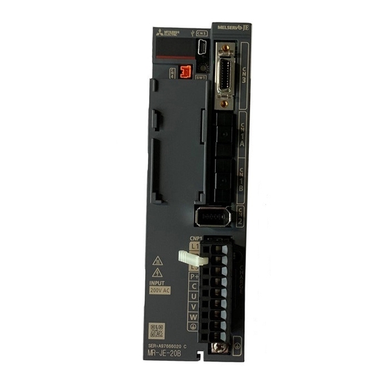
Summarization of Contents
1. Functions and Configuration
1.1 Summary
Overview of the MELSERVO-JE series servo amplifier functions and features.
1.2 Function Block Diagram
Illustrates the internal connections and signal flow of the servo amplifier.
1.3 Servo Amplifier Standard Specifications
Details electrical and environmental specifications for MR-JE servo amplifiers.
1.4 Combinations of Servo Amplifiers, Servo Motors, and Controllers
Lists compatible combinations of servo amplifiers, motors, and controllers.
1.5 Function List
A comprehensive list of functions available in the servo amplifier with detailed explanations.
1.7 Structure
Identifies and describes the various parts and connectors of the servo amplifier.
1.8 Configuration Including Peripheral Equipment
Shows typical connection diagrams with optional peripheral equipment.
2. Installation
CAUTION
General precautions for installation, handling, and environmental conditions.
2.1 Installation Direction and Clearances
Specifies correct installation orientation and required clearances for heat dissipation.
2.4 SSCNET III Cable Laying
Proper methods for routing SSCNET III optical fiber cables to avoid damage and ensure signal integrity.
2.5 Inspection Items
Periodic checks recommended for maintenance to ensure proper operation and safety.
2.6 Parts Having Service Life
Lists components with limited service life and their estimated lifespan.
3. Signals and Wiring
3.1 Input Power Supply Circuit
Details on correctly connecting the power supply, including essential components like magnetic contactors.
3.4 Connectors and Pin Assignment
Shows pin assignments for key connectors like CN1A, CN1B, CN2, CN3, CN4, and CN5.
3.5 Signal (Device) Explanations
Explains input and output signals, their functions, and relevant parameters for device configuration.
3.6 Forced Stop Deceleration Function
Details the function and operation of forced stop deceleration using EM2.
3.10 Servo Motor with an Electromagnetic Brake
Safety precautions and operational details for servo motors equipped with electromagnetic brakes.
3.11 Grounding
Essential guidelines and diagrams for proper grounding of the servo amplifier and motor for safety and noise reduction.
4. Startup
4.1 Switching Power On for the First Time
Step-by-step procedure for initial power-up and startup of the servo system.
4.2 Startup
Procedures for initial power-on, parameter setting, servo-on, and home position return.
4.4 Test Operation
Procedures for verifying servo operation independently of the machine.
4.5 Test Operation Mode
Explains the test operation modes available via MR Configurator2.
5. Parameters
CAUTION
Warnings against incorrect parameter changes that can lead to unstable operation or startup issues.
5.1 Parameter List
Provides an overview of parameter categories and notes on enabling parameters.
5.2 Detailed List of Parameters
Provides detailed explanations for basic setting parameters.
6. Normal Gain Adjustment
6.1 Different Adjustment Methods
Outlines different methods for adjusting servo gains.
6.2 One-Touch Tuning
Details the one-touch tuning function and its methods (user command, amplifier command).
6.3 Auto Tuning
Explains the auto tuning function and its modes (Auto tuning mode 1, Auto tuning mode 2).
6.4 Manual Mode
Describes how to manually adjust all gains when auto tuning is not satisfactory.
7. Special Adjustment Functions
7.1 Filter Setting
Introduces various filters available for suppressing vibration and resonance.
7.1.1 Machine Resonance Suppression Filter
Explains the purpose and application of machine resonance suppression filters.
7.2 Gain Switching Function
Describes the function to switch gains based on operating conditions for improved performance.
7.3 Tough Drive Function
Explains the tough drive function for continued operation under alarms.
7.5 Lost Motion Compensation Function
Explains how to compensate for response delays caused by mechanical factors.
8. Troubleshooting
8.1 Explanation for the Lists
Explains the columns used in alarm and warning lists, including stop methods and deactivation.
8.2 Alarm List
A comprehensive list of alarms, their details, stop methods, and deactivation procedures.
8.3 Warning List
A list of warnings, their details, and stop methods.
9. Dimensions
9.1 Servo Amplifier
Provides dimensional drawings and specifications for MR-JE servo amplifiers.
9.2 Connector
Shows dimensions for CN1A/CN1B and SCR connector systems.
10. Characteristics
10.1 Overload Protection Characteristics
Details the electronic thermal protection curves for servo motors and amplifiers against overloads.
10.3 Dynamic Brake Characteristics
Explains dynamic brake operation, coasting distance calculation, and time constants.
11. Options and Peripheral Equipment
11.1 Cable/Connector Sets
Lists recommended cables and connectors, and explains IP rating considerations.
11.2 Regenerative Option
Information on regenerative options, combinations, and power ratings.
11.4 MR Configurator2
Introduces MR Configurator2 software for parameter settings and diagnostics.
11.5 Battery
Information on batteries used for absolute position detection systems.
11.7 Molded-Case Circuit Breakers, Fuses, Magnetic Contactors
Recommendations for selecting circuit breakers, fuses, and magnetic contactors for safety.
11.10 Noise Reduction Techniques
General and specific techniques for reducing electrical noise affecting the servo amplifier and peripheral equipment.
11.12 EMC Filter (Recommended)
Recommends EMC filters for compliance with EN directives and shows connection examples.
12. Absolute Position Detection System
CAUTION
Warnings regarding absolute position data loss and battery handling.
12.1 Summary
Overview of the absolute position detection system and its features.
12.2 Battery
Information about batteries used for absolute position detection.
APPENDIX
App. 1 Peripheral Equipment Manufacturer (for Reference)
Lists manufacturers of recommended peripheral equipment.
App. 2 Handling of AC Servo Amplifier Batteries for the United Nations Recommendations on the Transport of Dangerous Goods
Regulations and guidelines for transporting lithium batteries.
App. 4 Compliance with Global Standards
Information on compliance with global standards like EMC and Low-voltage directives.
App. 4.3 Electrical Installation and Configuration Diagram
Representative configuration examples conforming to international electrical standards.
App. 4.4 Signals
Details the signals for the CN1 connector.
App. 4.5 Maintenance and Service
Recommendations for periodic inspections and maintenance.


Need help?
Do you have a question about the MR-JE-70B and is the answer not in the manual?
Questions and answers