
Related Manuals for Azbil AVP301


Summarization of Contents
Chapter 1: Control System Structure
1.1 System Configuration
Describes the device as a smart valve positioner connectable to a 4 to 20 mA signal line.
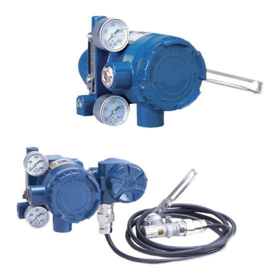
1.3 Description of Device Structure and Functions
Illustrates and explains the structure and functions of the device's main components.
Chapter 2: Installation
2.2 Installation Method
Provides general guidelines and points to consider for attaching the positioner to an actuator.
2.2.1 Attachment to actuator
Details on how to correctly attach the positioner to various types of actuators.
2.2.2 Air piping connection
Explains the procedure for connecting the air supply and output to the actuator.
2.2.4 Electrical Wiring Connection
Describes the methods for connecting the signal input and output wiring.
2.3 Remote Type Handling
Covers procedures for handling and connecting the remote type positioner cables.
Chapter 3: Operation
3.1 Auto-setup
Details the process of automatically setting the valve's fully closed and open positions.
3.2 Zero/Span Adjustment
Explains how to manually adjust the valve's zero and span points using external controls.
3.3 Starting Operation
Outlines the necessary pre-operation checks and procedures for starting up the device.
Chapter 4: Communication-Based Operation
4.2 Communication-Based Operation
Describes operations performed using communication software like CommStaff.
4.4 Device Configuration and Adjustment
Covers essential configuration and adjustment procedures for proper device operation.
4.4.1 Auto-setup
Details the auto-setup process for configuring key parameters automatically.
4.4.2 Zero/span adjustment
Explains the procedure for setting the valve's fully closed and open positions via communication.
4.6 Maintenance
Covers maintenance procedures such as mode modification and input calibration.
4.7 Valve Diagnostic Parameter Configuration
Details how to configure parameters for valve diagnostics like stick-slip and cycle count.
4.8 Self-diagnostics
Explains the device's self-diagnostics function and how to interpret failure messages.
Chapter 5: Maintenance and Troubleshooting
5.1 Troubleshooting
Provides guidance on identifying and resolving problems during startup or operation.
5.2 A/M Switch
Explains the function and operation of the Automatic/Manual switch.
Chapter 6: Cautions Regarding Explosion-proof Models
Cautions regarding explosion-proof models
Provides general safety precautions specific to explosion-proof models.
[1. TIIS flameproof]
Details installation location criteria and safety conditions for TIIS flameproof models.
[2. FM Explosion-proof]
Specifies installation criteria and hazards for FM explosion-proof models.
[4. ATEX flameproof]
Covers ATEX flameproof certifications, standards, and safe use instructions.
Appendix A: Specifications
FUNCTIONAL SPECIFICATIONS
Lists key functional specifications including actuator types, input/output signals, and air consumption.
Model Number Configuration
Details the coding system for configuring model numbers based on features and options.
Dimensions (Model AVP300/301/302)
Provides dimensional drawings for single-acting and double-acting actuators.
Terms and Conditions
1. Warranty period and warranty scope
Outlines the warranty period and the scope of coverage for Azbil Corporation's products.
2. Ascertainment of suitability
Emphasizes the user's responsibility to ascertain product suitability for their application.
3. Precautions and restrictions on application
Lists precautions and restrictions for using products in specific applications or environments.
Need help?
Do you have a question about the AVP301 and is the answer not in the manual?
Questions and answers