
Subscribe to Our Youtube Channel
Related Manuals for Azbil 700 Series


Summary of Contents for Azbil 700 Series
- Page 1 CM2-AVP703-2001 Smart Valve Positioner 700 Series with F Fieldbus OUNDATION Model AVP703 User's Manual...
- Page 2 • We can not take responsibility for any unexpected results that are the result of your handling of the product. ™ • F Fieldbus is a trademark of the FieldComm Group. OUNDATION © 2014–2019 Azbil Corporation. All Rights Reserved.
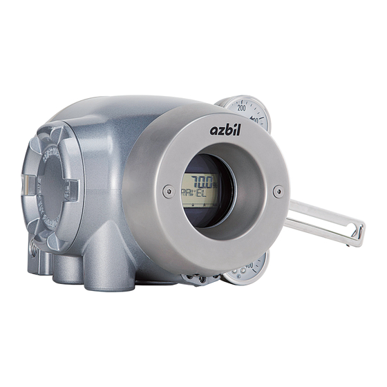
- Page 3 Introduction Thank you for purchasing our AVP703 Smart Valve Positioner. The AVP703 (called “the device” below) is a smart valve positioner that can be connected to the Foundation Fieldbus. The auto setup function makes it easy to set up the valve. All adjustments and setup can be performed from the Foundation Fieldbus host.
- Page 4 Safety precautions Symbols The purpose of the safety precautions listed here is to ensure the user uses the product safely and correctly, to prevent harm to the user and other people and damage to property. Make sure to observe the safety precautions. Many different symbols are used in this manual.
- Page 5 Precautions for safe work WARNING Do not perform wiring with wet hands or while the device is energized. This may lead to electric shock. Turn the power off before starting the work and work with dry hands or use gloves. Follow the work procedure defined in the explosion protection guidelines when performing the power distribution work in an explosion-proof area.
- Page 6 Unpacking, Verification, and Storage of Product Unpacking This device is precision measuring equipment. Carefully handle it to prevent accidents or damage. After unpacking, check that the items below are included. • The device • Feedback lever and hexagon socket bolts×2 •...
-
Page 7: Table Of Contents
Installation of the 700 Series 2-1. Usage Conditions 2-2. Selection Criteria for Installation Location 2-2-1. Selection Criteria for Installation Location 2-3. Installation Procedure 2-3-1. Mounting the 700 Series onto the Actuator 2-3-2. Pneumatic Piping Connection 2-11 2-3-3. Electrical Wiring Connection 2-14 2-3-4. - Page 8 6-3. Cleaning the Flapper 6-4. Adjusting the Pilot Relay 6-5. Insulation Resistance Test 6-6. Adjustment Procedure When Using the Device with the Booster Relay Attached 6-7. Internal Block Diagram of the 700 Series 6-8. Resale Parts 6-8-1. Procedure to Change Switch Block 6-12 6-8-2.
-
Page 9: Chapter 1. Structure Of The 700 Series Control System
The concept and the operation block diagram of the control valve control system that uses the device are shown below. Air to the actuator Fieldbus Other Fieldbus device Device Supply air Air supply system Process fluid Shutoff Solenoid valve valve with filter Control valve Figure 1-1. Concept Diagram of the 700 Series Control System... - Page 10 Chapter 1 Structure of the 700 Series Control System 1) Operation block diagram The block configuration of a typical function block and positioner is shown in the figure below. Fieldbus Resource Block Positioner Transducer Function Block Block − Positioner control section...
-
Page 11: Structure Of The Device And Description Of Each Part
Chapter 1 Structure of the 700 Series Control System 1-2. Structure of the Device and Description of Each Part 1-2-1. Structure of the Device 1) Major components The structure of the main unit of the device is shown in the figure below. - Page 12 Chapter 1 Structure of the 700 Series Control System 2) Name and description of each part The table below describes each part. Table 1-1. Description of Each Part Name Description • Houses electronic circuits, an electro-pneumatic trans- Main unit ducer (EPM), a position sensor (VTD), and a pressure sensor.
-
Page 13: Structure Of Terminal Box
Chapter 1 Structure of the 700 Series Control System 1-2-2. Structure of Terminal Box 1) Major components The terminal box houses the Fieldbus terminal and the internal grounding terminal. The structure of the terminal box is as shown below. Lock screw... - Page 14 Chapter 1 Structure of the 700 Series Control System 2) Name and description of each part The table below describes each part of the terminal box. Table 1-2. Description of Each Part Name Description • Lid of terminal box. Terminal box cover •...
-
Page 15: Display On The Local User Interface (Lui)
Chapter 1 Structure of the 700 Series Control System 1-2-3. Display on the Local User Interface (LUI) (10) Figure 1-7. Segments on the LUI Table 1-3. Description of Each Part Displayed element Main display Displays the main numerical values such as the speci- (1) 7 segments (5 digits) fied opening. - Page 16 Chapter 1 Structure of the 700 Series Control System...
-
Page 17: Chapter 2. Installation Of The 700 Series
Chapter 2 Installation of the 700 Series Chapter 2. Installation of the 700 Series This chapter describes the usage conditions, installation, piping, and wiring of the device. Precautions for safe work WARNING Do not perform wiring with wet hands or while the device is energized. This may lead to electric shock. -
Page 18: Usage Conditions
Chapter 2 Installation of the 700 Series 2-1. Usage Conditions The device must be installed in the location, which satisfies the following conditions. Also, the divice must be used in accordance with its specification. Table 2-1. Range of Usage Conditions... -
Page 19: Selection Criteria For Installation Location
Chapter 2 Installation of the 700 Series 2-2. Selection Criteria for Installation Location The device is designed to withstand severe conditions, but the installation location should be selected according to the criteria described below to maximize performance. 2-2-1. Selection Criteria for Installation Location Install the device in a location that satisfies all of the following conditions. - Page 20 Chapter 2 Installation of the 700 Series <Example devices> Products from SMC Corporation • Mist Separator AM150 or AM250 Series (Filtering level: 0.3 μm, Secondary oil mist concentration: 1.0 mg/m CKD Corporation • Oil mist filter • M1000 or M3000 Series •...
-
Page 21: Installation Procedure
Chapter 2 Installation of the 700 Series 2-3. Installation Procedure 2-3-1. Mounting the 700 Series onto the Actuator The device is a smart valve positioner for use with a control valve that uses a direct-acting or rotary actuator. The main unit of the device weighs approximately 4.2 kg. The basic mounting procedure is the same as that for conventional electropneumatic positioners. - Page 22 [Direct-Acting Actuator HA2 to 4, PSA1 to 4, 6, VA1 to 6 from Azbil Corporation] Yoke Hexagon socket ange bolts (×2) Connector pin assembly Feedback pin Plain washer Feedback lever Spring washer Hexagonal bolt Figure 2-3. Mounting Procedure for Direct-Acting Actuator HA2 to 4, PSA1 to 4, 6, VA1 to 6 from Azbil Corporation...
- Page 23 [RSA1, 2, VR3 actuator from Azbil Corporation] Plain washer Feedback pin Spring washer Feedback lever Hexagonal bolt Figure 2-4. Mounting Procedure for RSA1, 2, VR3 Actuator from Azbil Corporation [Example of double-acting rotary cylinder actuator] Spacer Spring washer Hexagonal bolt Spring washer...
- Page 24 Chapter 2 Installation of the 700 Series 4) Connection of feedback pin and feedback lever (1) There are several points to be careful of when connecting the feedback lever to the device and the actuator feedback pin. Connect correctly. •...
- Page 25 When assembling the lever onto a rotary cylinder so that the shaft of the rotary cylinder is positioned between the feedback pin and the 700 Series as shown in the figure below, select Rotary/90° (for 90°) or Rotary/other (for angles other than 90°) as the Actuator Type according to the rotation angle.
- Page 26 Chapter 2 Installation of the 700 Series 6) Installing the device with the LCD facing upwards If you install the device with the LCD facing upwards, use the accessories below as re- quired depending on the circumstances. (Refer to 6-9, “Resale Parts. ” ) •...
-
Page 27: Pneumatic Piping Connection
• Install the solenoid valve so that the drain faces downward. • If you select the built-in Azbil solenoid valve KZ03, the filter is built into the device be- fore shipment. 4) Shutoff valve • The shutoff valve is used to temporarily stop supplying air to the device. - Page 28 Chapter 2 Installation of the 700 Series 5) Piping • Use piping with an inside diameter of 6 mm. • When using the device in a corrosive atmosphere, select piping appropriate to the environ- ment of the installation location. For example, you may use the vinyl-coated copper pipe.
- Page 29 Chapter 2 Installation of the 700 Series 7) Mounting procedure The procedure for connecting pneumatic piping to operate the device is shown below. Step Description Connect the joint for piping to the connection port using seal tape. Handling Precautions: •...
-
Page 30: Electrical Wiring Connection
Turn the power off before starting wiring work. Otherwise, electric shock may occur. When using the explosion-proof 700 Series in a dangerous place, be sure to connect the wiring while following “Chapter 7. Notes on the Explosion-Proof 700 Series. ”... - Page 31 Chapter 2 Installation of the 700 Series 2) Terminal for external grounding Connect the external grounding terminal to the case with two washers as follows. Cable lug Washer Washer Figure 2-17. Connection of External Grounding Terminal 3) How to install a Fieldbus network There are two ways to install a fieldbus network.
-
Page 32: Cables
Chapter 2 Installation of the 700 Series 4) Precautions for installing cables Note the following points when installing a cable. • Route the cable so as to avoid high-capacity transducers, motors, power supplies for engines, or other devices that generate noise. Do not put a cable in the same tray or duct as a cable for an engine. - Page 33 Chapter 2 Installation of the 700 Series 3) Wiring procedure The procedure for electrical wiring to operate the device is shown below. Step Description Turn off the Fieldbus power supply. Rotate the lock screw (M4) on the terminal box cover with a (3-mm) hexagonal wrench clockwise to loosen it.
-
Page 34: Cable Gland And Flameproof Universal Elbow For Tiis Flameproof Apparatus
Chapter 2 Installation of the 700 Series 2-4. Cable gland and flameproof universal elbow for TIIS Flameproof apparatus TIIS Flameproof SVP model is provided with a certified cable gland. The cable gland seals the cable entering the SVP enclosure to withstand an internal explo- sion and protects the cable from being damaged mechanically and electrically. - Page 35 Chapter 2 Installation of the 700 Series 2) Structure of the flameproof universal elbow The figure below shows the universal elbow. Lock nut Elbow O-ring Figure 2-21. Flameproof elbow 3) Mounting example The flameproof cable gland and the universal elbow are used to connect the field wiring cable to the device enclosure, as shown below.
- Page 36 Chapter 2 Installation of the 700 Series 4) Mounting procedure for flameproof cable gland The procedure for mounting the flameproof cable gland is shown below. Step Description Securely screw the main unit of the adapter into the conduit connection port of the terminal box or into the flameproof universal elbow, and fasten the hexagon socket bolt.
- Page 37 Chapter 2 Installation of the 700 Series 5) Mounting procedure for flameproof universal elbow The procedure for mounting the flameproof universal elbow is shown below. Step Description Align the end surface of the lock nut with the end surface of the O-ring groove as shown below.
- Page 38 Chapter 2 Installation of the 700 Series 2-22...
-
Page 39: Chapter 3. Operation Of The 700 Series
This chapter describes how to start operating the device and adjust the device using the local user interface (LUI). When you purchase the device alone, be sure to read “Installa- tion of the 700 Series” before reading this chapter. Precautions for safe work WARNING Do not perform wiring with wet hands or while the device is energized. -
Page 40: Local User Interface (Lui)
Chapter 3 Operation of the 700 Series 3-1. Local User Interface (LUI) Four push buttons on the LUI (with , and symbols) can be operated by removing two screws ((2.5-mm) hexagonal socket bolts) from the front cover of the device. - Page 41 Chapter 3 Operation of the 700 Series The LUI displays the dynamic values in the device and can be used to adjust and set up the following six functions. • Auto setup function • Zero span adjustment • Supply pressure bypass function •...
-
Page 42: Displays
Chapter 3 Operation of the 700 Series 3-1-1. Displays If you use another host or communicator for communication during setup, this screen is displayed and the setup mode cannot be started. Hold down Setup mode Setup mode Monitor mode Monitor mode... -
Page 43: Disp_Tb Display
Chapter 3 Operation of the 700 Series 3-1-2. Disp_TB Display 1) Display at startup The display changes as follows at startup: (1) All segments are lit (approx. 0.8 s) → (2) All segments are turned off (approx. 0.8 s) → (3) Normal monitor Disp_TB display (“FF_DISCON”) (approx. 10 s) → (4) Normal moni- tor Disp_TB display (“DSP_OOS”) (approx. - Page 44 Chapter 3 Operation of the 700 Series Table 3-2. Parameters that can be displayed Block Profile Number Parameter Index Range Index Positioner TB 0x0145 FINAL_VALUE FINAL_VALUE_RANGE FINAL_POSITION_VALUE FINAL_VALUE_RANGE WORKING_POS FINAL_VALUE_RANGE WORKING_SP FINAL_VALUE_RANGE PID FB 0x0108 OUT_SCALE PV_SCALE CAS_IN PV_SCALE BKCAL_IN...
- Page 45 Chapter 3 Operation of the 700 Series With the above configuration, the parameters are displayed cyclically in the following se- quence. Sequence Numerical value section Character string section Display duration WORKING_SP value W_SP (Tag) WORKING_SP value % (Unit) WORKING_SP value...
- Page 46 Chapter 3 Operation of the 700 Series 4) Status indication For the status indicated in the character string section, see Table 3-3, “Indicated status, ” below. Table 3-3. Indicated status Quality Substatus Units displayed Description 0: Bad Bad_0 Non-specific Bad_1...
- Page 47 Chapter 3 Operation of the 700 Series Table 3-4. Units displayed on the LCD Unit Unit code Display Description UNIT_K 1000 Kelvin UNIT_degC 1001 degC degree Celsius UNIT_degF 1002 degF degree Fahrenheit UNIT_degR 1003 degR degree Rankine UNIT_m3 1034 cubic meter...
- Page 48 Chapter 3 Operation of the 700 Series Unit Unit code Display Description UNIT_kg_d 1325 kg/d kilogram per day UNIT_t_s 1326 metric ton per second UNIT_t_m 1327 metric ton per minute UNIT_t_h 1328 metric ton per hour UNIT_t_d 1329 metric ton per day...
- Page 49 Chapter 3 Operation of the 700 Series Unit Unit code Display Description UNIT_Mgal_m 1455 Mgal/m mega US gallon per minute UNIT_mgal_h 1457 mgal/h milli US gallon per hour UNIT_kgal_h 1458 kgal/h kilo US gallon per hour UNIT_Mgal_h 1459 Mgal/h mega US gallon per hour...
- Page 50 Chapter 3 Operation of the 700 Series Unit Unit code Display Description UNIT_NL_m 1533 NL/m Normal liter per minute UNIT_NL_h 1534 NL/h Normal liter per hour UNIT_NL_d 1535 NL/d Normal liter per day UNIT_SL_s 1537 SL/s Standard liter per second...
- Page 51 Chapter 3 Operation of the 700 Series 7) Alarms If an error or failure occurred, the following alarms will be indicated cyclically. Table 3-5. Indicated alarms FD_xxx_ACTIVE Bit Units displayed Description Check T.B.D. FST Exe Full Stroke Test is Executing...
-
Page 52: Adjustment Before Operation
Chapter 3 Operation of the 700 Series 3-2. Adjustment before Operation Perform auto setup before using the device. Then, adjust the zero span if necessary. The zero span adjustment function in the device electrically sets the fully closed and fully open positions of the valve independently of each other. - Page 53 Chapter 3 Operation of the 700 Series • When the device is purchased separately, its initial settings are set to those in the list of default values in “Appendix C Parameter List” of this manual. Because the default actuator direction is reverse, if you mount the device on the direct actua- tor the device will not work.
- Page 54 Chapter 3 Operation of the 700 Series (1) Procedure for performing auto setup Step Description LUI display Loosen two (2.5-mm) hexagonal socket bolts and remove the front cover. (A sample initial setup status of the LUI screen is shown.) Hold down the button to start the setup mode.
-
Page 55: Zero Span Adjustment
Chapter 3 Operation of the 700 Series (3) Procedure for specifying Actuator Type and Valve Closed Position Step Description LUI display Start the setup mode and display the screen on the right by re- peatedly pressing the button. Press the button. - Page 56 Chapter 3 Operation of the 700 Series (1) Procedure for adjusting the zero span Step Description LUI display Set Target for MODE_BLK to MAN (Manual) in the Positioner Transducer Block and specify the desired opening value (0% or 100%) in FINAL_VALUE.
- Page 57 Chapter 3 Operation of the 700 Series (2) Procedure for adjusting the angle Step Description LUI display Select the angle (COARSE, MID, FINE) for 100% opening ad- justment (0% opening adjustment) with the buttons and press the button. COARSE: Angle 1°...
-
Page 58: Supply Bypass
Chapter 3 Operation of the 700 Series 3-2-3. Supply Bypass Supply bypass allows the valve to be fully closed and opened and enables operation with the solenoid valve. (For double-acting actuators, the valve can only be fully opened or closed.) CAUTION When the supply bypass operates, it is dangerous because the valve moves. -
Page 59: Control Parameters
Chapter 3 Operation of the 700 Series 3-2-4. Control Parameters Control parameters are determined by Actuator Size (PARAM 1 to 6, A, B, C) and Friction Level (Light (L), Medium (M), Heavy (H)). Table 3-6. Actuator Size Typical actuator Actuator capacity... - Page 60 Chapter 3 Operation of the 700 Series (1) Procedure for specifying control parameters Step Description LUI display Loosen two (2.5-mm) hexagonal socket bolts and remove the front cover. Hold down the button to start the setup mode. Press the button to display the screen shown on the right (tune).
-
Page 61: Starting Operation
Chapter 3 Operation of the 700 Series 3-3. Starting Operation 3-3-1. Checking Fieldbus Operation Check the operation of the device in combination with Fieldbus. It is necessary to input the DD (device description) file and the CF (capability) file for the device in the host before operating Fieldbus. -
Page 62: Preoperation Check
Chapter 3 Operation of the 700 Series 3-3-2. Preoperation Check Check the following points before starting operation. • The device is properly installed and the feedback lever, feedback pin and other parts are not damaged or fractured. • The pneumatic piping is completely connected and an appropriate supply air pressure is supplied. -
Page 63: Chapter 4. Operations Using Fieldbus Communication
This is the menu for each block in the host (PC) that can display the block menu and displays the parameters for setup, adjustment, and other operations of the positioner. (Example: Device Management System, InnovativeField Organizer, from Azbil) • Parameter list The parameter list displays all the parameters by block. -
Page 64: Process Variables
Chapter 4 Operations Using Fieldbus Communication 4-2-1. Process Variables The measurement value data present when the device is operating can be viewed. You can view the following items by selecting [Process Variables]. Table 4-1. Description of Each Part Item Description Final Value Status Displays the status (Status) and value (Value) of input signals to the device. - Page 65 Chapter 4 Operations Using Fieldbus Communication • In some cases, the initial setting is not same even though the actuator and valve size is same. Please perform the operation check and configuration of the device if necessary. • There is a possibility that the forced open value described on page “4-2-6 Final Value Cutoff ”...
-
Page 66: Valve System
Chapter 4 Operations Using Fieldbus Communication (5) Specification of Positioner Action The positioner operation is forward operation (Direct) if the output air pressure at power-off is 0. The positioner operation is reverse operation (Reverse) if the output air pressure at power-off is the supply air pressure. -
Page 67: Control Configuration
Chapter 4 Operations Using Fieldbus Communication • Air Fail To Open or Closed is automatically set as the fail safe direction when the supply air pres- sure is “Disconnected” based on the settings for Valve Closed Position and Feedback Lever Motion. This item is not displayed when Pilot Relay Type is Double Acting. -
Page 68: Characterization
Chapter 4 Operations Using Fieldbus Communication • Control Parameters When Actuator Size is Custom, each PID must be specified individually. The control algorithm employs dual GAP PID control, which switches PID parameters between three levels depending on the control deviation size. There are 11 parameters as shown below. -
Page 69: Final Value Cutoff
Chapter 4 Operations Using Fieldbus Communication 4-2-6. Final Value Cutoff Specify the input signal (%) to forcibly fully open or close the valve. The valve is fully closed when the input signal is less than or equal to the forced fully closed value. The valve is fully opened when the input signal is greater than or equal to the forced fully open value. -
Page 70: Travel Calibration
Chapter 4 Operations Using Fieldbus Communication 4-2-8. Travel Calibration Adjust zero and span of valve opening. Select [Device]→[Maintenance]→[Travel Calibration]. The following four types of zero span adjustment methods are available. (1) Auto Travel Calibration (2) Angle Correction (3) Manual Setting (4) Change Travel Angle Handling Precautions: If you adjust the span after auto setup, the forced fully open value is changed to... -
Page 71: Pressure Sensor Adjustment
Chapter 4 Operations Using Fieldbus Communication (3) Manual Setting Manually fix the 0% or 100% opening and set the zero and span points. Select [Device]→[Maintenance]→[Travel Calibration]→[Manual Setting]. • 0% Travel Move the valve to the 0% opening position by operating the input signal, actuator pressure, manual handle, or other factor and set the zero point. -
Page 72: Test
Chapter 4 Operations Using Fieldbus Communication 4-2-11. Test The two types of tests are Partial Stroke Tests and Full Stroke Tests. Set VST_MODE to either PST or FST to perform PST or FST. (1) Partial Stroke Test Configure the settings for the partial stroke test. Select [Device]→[Valve Stroke Test]→[Partial Stroke Test]. -
Page 73: Restore Factory Settings
Chapter 4 Operations Using Fieldbus Communication (2) Full Stroke Test Configure settings for the fully close/fully open operation test. Select [Device]→[Maintenance]→[Full Stroke Test]. • FST Enabled Enables or disables the FST start command. • FST Pause Time Wait time after the opening reaches the setting value. This setting also applies to the •... -
Page 74: Device Information
Chapter 4 Operations Using Fieldbus Communication 4-2-14. Device Information Select [Device]→[Device Information]. The following setting information can be viewed and changed. Item Description Manufacturer Id Manufacturer ID Device Type Device type ITK Version ITK version. Device Revision Device revision DD Revision DD revision Hardware Revision Hardware revision... -
Page 75: Diagnostic Messages
Chapter 4 Operations Using Fieldbus Communication 4-3. Diagnostic Messages The device has a self-diagnostic function. Select [Diagnostics]→[Diagnostics Status]→[Positioner Diagnostic Status]. 4-3-1. Self-Diagnostic Messages English Failure Valve Travel Detector Failure Valve Travel Detector Out of Range CPU Failure RAM Failure ROM Failure A/D Conversion Module 1 Failure A/D Conversion Module 2 Failure Non-Volatile Memory Failure... - Page 76 Chapter 4 Operations Using Fieldbus Communication Self-diagnostic messages pertaining to fail-safe operation If the device judges, based on the result of self-diagnosis, that it cannot control the valve properly, the device executes fail-safe operation. The output air pressure during fail-safe operation are as follows. Positioner action Pilot Relay Type Output Air Pressure...
-
Page 77: Control Valve Diagnostic Messages
Chapter 4 Operations Using Fieldbus Communication 4-3-2. Control Valve Diagnostic Messages The device has a control valve diagnostic function. Select [Diagnostics]→[Diagnostics Status]→[Valve Diagnostic Status]. English Out of Specification Supply Pressure High Alarm Supply Pressure Low Alarm Temp High Alarm Temp Low Alarm Deviation +Alarm Deviation −Alarm Zero Travel +Alarm... - Page 78 Chapter 4 Operations Using Fieldbus Communication 4-16...
-
Page 79: Chapter 5. Troubleshooting
Chapter 5 Troubleshooting Chapter 5. Troubleshooting This chapter describes how to address problems in case of troubles. The following three types of problems may occur when you start up and start operating the device. • Problems that occur because the specifications of the device are not suitable for the ac- tual use conditions •... -
Page 80: Troubleshooting
If the problem cannot be solved after taking the actions described below, the device may be malfunctioning. In that case, contact the Azbil group. 5-1-1. The Device Does Not Operate. (There Is No Output Air Pressure.) 1. -
Page 81: The Control Valve Operates Abnormally (There Is Output Air Pressure.)
Chapter 5 Troubleshooting 5-1-2. The Control Valve Operates Abnormally (There Is Output Air Pressure.) 1. Activate the manual operation status with the A/M switch, adjust air with the sole- noid valve, and check that the valve shaft moves smoothly. (Check whether galling or packing solidification has occurred.) 2. -
Page 82: Adjustment Procedure When Hunting Occurs
Chapter 5 Troubleshooting 5-1-4. Adjustment Procedure When Hunting Occurs Start adjustment Hunting event confirmed Auto Does hunting still occur The AVP is normal. Is the control loop Adjust the control after the controller controller auto or manual? loop again. is set to manual? Manual Change the hysteresis, which is a control parameter for the AVP positioner, from Light to Medium to Heavy or in the direction in which the actuator... -
Page 83: Auto Setup Failure
Chapter 5 Troubleshooting 5-1-5. Auto Setup Failure Check the following: • The supply air pressure is appropriate. • The A/M switch is in the AUTO position. • The feedback pin and feedback lever are properly connected. • The output air pressure is properly supplied to the actuator. •... -
Page 84: Description Of Messages
RAM error. Contact Azbil group. 0x0b, 0x0E, 0x0F Non-Volatile 0x04, 0x05, 0x06, Memory Failure AL_00 0x07, 0x0c, 0x0d, Non-volatile memory error. Contact Azbil group. 0x0E, 0x0F CPU Failure 0x08, 0x09, 0x0A, 0x0b, AL_00 CPU error. Contact Azbil group. 0x0c, 0x0d, 0x0E,... - Page 85 0x*8, 0x*9, 0x*A, The temperature in the conditions. If this message is AL_03 0x*b, 0x*c, 0x*d, device is lower than −40°C displayed even though this 0x*E, 0x*F or higher than 80°C. condition is satisfied, a sensor error is suspected. contact Azbil group.
- Page 86 AL_03 0x1*, 0x5* lower than 50 kPa or higher message is displayed even than 715 kPa. though this condition is satisfied, a sensor error is suspected. Contact Azbil group. Supply Pressure • Check the supply air pressure. The supply air pressure is High Alarm...
- Page 87 Chapter 5 Troubleshooting LUI display LUI display Message Description and cause Action Upper Lower part example part (*: Optional) Max Tvl Speed 0x*1, 0x*3, 0x*5, The maximum operation Check the operation of the −Alarm AL_17 0x*7, 0x*9, 0x*b, speed − is smaller than the control valve.
- Page 88 Chapter 5 Troubleshooting LUI display LUI display Message Description and cause Action Upper Lower part example part (*: Optional) PST Incomplete The PST did not end The PST did not end normally. AL_19 0x1* normally. Check the operation. Stick-Slip in Stick-slip was detected AL_19 0x2* while the PST was Check for stick-slip operation.
- Page 89 Chapter 5 Troubleshooting LUI display LUI display Message Description and cause Action Upper Lower part example part (*: Optional) PST Timeout Change of opening was not detected within the specified time. The target opening was not The PST did not end normally. —...
- Page 90 Chapter 5 Troubleshooting 5-12...
-
Page 91: Chapter 6. Maintenance
Chapter 6 Maintenance Chapter 6. Maintenance This chapter describes periodic maintenance for the device. You can properly use the de- vice by performing appropriate maintenance. In addition, the limited life parts are listed as resale parts in 6-8. Because the replacement frequencies of resale parts differ depending on the usage environment and usage situation of the device, specify appropriate replacement frequencies. -
Page 92: A/M Switch
Chapter 6 Maintenance 6-1. A/M Switch The maintenance work can be performed by switching between Auto and Manual. The de- vice has a built-in Auto/Manual (A/M) switch. The A/M switch switches the control method of output air from the positioner between auto operation and manual operation. -
Page 93: Replacement Of Filter And Maintenance Of Flow Restrictor
Chapter 6 Maintenance 5) Procedure for switching from manual operation to auto operation The procedure for switching from auto operation to manual operation is shown below. Step Description Securely rotate the A/M switch clockwise (in the AUTO direction) using a flat- head screwdriver until it stops. -
Page 94: Cleaning The Flapper
Chapter 6 Maintenance 6-3. Cleaning the Flapper CAUTION If air pressure is supplied to the device, the back pressure of the nozzle changes after the flapper is cleaned, and therefore, the valve opening suddenly changes. Perform cleaning under conditions where the sudden move of the valve will not injure people or disturb plant operation. If the flapper is contaminated by instrumentation air, clean it as described below. -
Page 95: Adjusting The Pilot Relay
Chapter 6 Maintenance 6-4. Adjusting the Pilot Relay The adjustment method for the pilot relay differs depending on whether the single-acting or double-acting actuator is used. Perform adjustments suitable for the actuator being used by referring to the procedures described below. CAUTION When rotating the pilot relay adjustment screw, be careful not to get your finger caught in the space between it and the adapter. -
Page 96: Insulation Resistance Test
Chapter 6 Maintenance 2) Procedure for adjusting the pilot relay for the single-acting actuator (Ad- justment from double-acting type to single-acting type) Step Description Rotate the pilot relay adjustment screw counterclockwise (loosening direction) until it stops. Output air pressure Pout2 becomes 0. Perform auto setup. -
Page 97: Adjustment Procedure When Using The Device With The Booster Relay Attached
Chapter 6 Maintenance 6-6. Adjustment Procedure When Using the Device with the Booster Relay Attached When using the device with the booster relay attached, perform adjustment according to the following procedure. Start adjustment Properly connect the pneumatic piping to the connection Assemble the device and ports on the device and the booster relay. -
Page 98: Internal Block Diagram Of The 700 Series
Chapter 6 Maintenance 6-7. Internal Block Diagram of the 700 Series 1) Internal block diagram of the 700 Series AVP703 Pilot relay Actuator Valve Actuator Valve plug Positioner Input Forcibly fully Flow amount Air signal control forward/ forward/ forward/ signal... - Page 99 Chapter 6 Maintenance Recommended Recommended Name Part no. Qty. replacement tightening period (year)* torque N·m Cross recessed head screws with cap- tive spring washers (for pilot relay, 398-204-250 — 1.8 ±0.2 M4×25) 19 O-ring (AS568-014) (for pilot relay) 80020935-409 — 20 O-ring (S7) (for pilot relay) 80020935-323 —...
- Page 100 Chapter 6 Maintenance Ask our service representative to replace the parts in the table below. Expertise is required to replace these parts. CAUTION Do not replace or desorb the parts in the table below, because it causes the device damage. When you replace or desorb it, ask our service representative to replace the parts.
- Page 101 Chapter 6 Maintenance Recommended Recommended Name Part no. Qty. replacement tightening period (year)* torque N·m <Except for structure L,T> 80388935-001 60 Sensor board — — <Structure L,T> 80384101-001 61 Sensor cable 80388944-001 — — O-ring (AS568A-013) (for pressure 80388829-013 — sensor) Hexagon socket bolt with captive spring washer (for sensor cover,...
-
Page 102: Procedure To Change Switch Block
Chapter 6 Maintenance 6-8-1. Procedure to Change Switch Block Step Description Loosen two screws with a hexagon socket screw keys and remove the face cover (Figure 6-6) Loosen two screws and remove the face cover (Figure 6-7) Tighten a new switch block with two screws. (Torque: 1.02 ±0.33 N·m) Press four buttons and make sure whether the display changes or not. -
Page 103: Procedure To Change Pilot Relay
Chapter 6 Maintenance 6-8-2. Procedure to Change Pilot Relay Step Description Loosen three screws and remove the P cover. (Figure 6-8) Loosen four screws and remove the pilot relay. (Figure 6-9) Tighten a new pilot relay with four screws. (Torque: 1.8 ±0.2 N·m) Tighten the P cover with three screws. - Page 104 Chapter 6 Maintenance 6-14...
-
Page 105: Chapter 7. Notes On The Explosion-Proof 700 Series
Apply the correct supply air pressure in accordance with the specification of the device. The over- pressure may cause abnormal actions of the control valve or damage to the pressure gauge. When using the explosion-proof 700 Series, sufficiently understand the notes in this sec- tion and use it correctly. -
Page 106: Tiis Flameproof Model
Explosion-Proofing 1985)” issued by the Technology Institution of Industrial Safety. Apply the correct supply air pressure in accordance with the Section 2-1 Usage Conditions Installa- tion of the 700 Series. Incorrect pressure may cause abnormal actions of the control valve or damage to the pressure gauge. -
Page 107: Atex Flameproof And Dust Ignition Protection
Chapter 7 Notes on the Explosion-Proof 700 Series 7-2. ATEX Flameproof and Dust Ignition Protection Ignition Protection 2012 Caution or A4-70. Caution This product is shipped with the IECEx certified blanking element only to avoid ingress of solid foreign objects and water during transportation, the certification of this product does not include the blanking element. - Page 108 Chapter 7 Notes on the Explosion-Proof 700 Series 2-3-3 This product is shipped with the IECEx certified blanking element only to avoid ingress 4.10 of solid foreign objects and water during transportation, the certification of this product does not include the blanking element.
-
Page 109: Iecex Flameproof And Dust Ignition Protection
Chapter 7 Notes on the Explosion-Proof 700 Series 7-3. IECEx Flameproof and Dust Ignition Protection Ignition Protection Caution or A4-70. Caution This product is shipped with the IECEx certified blanking element only to avoid ingress of solid foreign objects and water during transportation, the certification of this product does not include the blanking element. - Page 110 Chapter 7 Notes on the Explosion-Proof 700 Series 2-3-3 This product is shipped with the IECEx certified blanking element only to avoid 4.10 ingress of solid foreign objects and water during transportation, the certification of this product does not include the blanking element.
-
Page 111: Fm Explosionproof/Dust Ignition Protection
Chapter 7 Notes on the Explosion-Proof 700 Series 7-4. FM Explosionproof/Dust Ignition Protection 1. Explosionproof Class I, Division 1, Group B, C and D T6; 2. Flameproof Class I, Zone 1, AEx d IIC T6 Gb 3. Dust ignition Class II and III, Division 1, Group E, F, and G T6, Zone 21, AEx tb II C T85°C Db Ambient temperature: −30 to +75°C... -
Page 112: Fm Intrinsically Safe (Ic) And Nonincendive
Chapter 7 Notes on the Explosion-Proof 700 Series 7-5. FM Intrinsically safe (ic) and Nonincendive 1. Intrinsically safe (ic) Class I, Zone 2, AEx ic IIC T4 FISCO & Entity Parameters: Ui=32V, Ci=4nF, Li=0 2. Nonincendive Class I, Division 2, Group A, B, C and D, T4 Nonincendive Field Wiring &... - Page 113 Chapter 7 Notes on the Explosion-Proof 700 Series...
- Page 114 Chapter 7 Notes on the Explosion-Proof 700 Series 7-10...
-
Page 115: Fmc Explosionproof/Dust Ignition Protection
Chapter 7 Notes on the Explosion-Proof 700 Series 7-6. FMC Explosionproof/Dust Ignition Protection 1. Explosionproof Class I, Division 1, Group C and D T6; 2. Flameproof Class I, Zone 1, Ex d IIB T6 Gb 3. Dust ignition Class II and III, Division 1, Group E, F, and G T6;... -
Page 116: Nepsi Flameproof/Dust Ignition Protection
Chapter 7 Notes on the Explosion-Proof 700 Series 7-7. NEPSI Flameproof/Dust Ignition Protection 1. Marking information Ex d IIC T6 Gb −30°C≤Tamb≤+75°C IP66 DIP A21 T 85°C IP66 2. Applicable standards • GB3836.1-2010 • GB3836.2-2010 • GB12476.1-2010 3. Special conditions for safe use •... - Page 117 Chapter 7 Notes on the Explosion-Proof 700 Series 4.10 This product is shipped with the IECEx certified blanking element only to avoid ingress of solid foreign objects and water during transportation, the certi- fication of this product does not include the blanking element. When installed, check the conformity of the blanking element to the relevant standards.
-
Page 118: Kosha Flameproof
Chapter 7 Notes on the Explosion-Proof 700 Series 7-8. KOSHA Flameproof 1. Marking information Ex d IIC T6 −30°C<T <+75°C 2. Special conditions for safe use Caution • The gap between the shaft for magnetic pass and the pneumatic module body has 0.065 mm max. -
Page 119: Inmetro Flameproof/Dust Ignition Protection
Chapter 7 Notes on the Explosion-Proof 700 Series 7-9. INMETRO Flameproof/Dust Ignition Protection Equipamento à prova de explosão do INMETRO Segurança Sobre este manual Este manual contém informações e advertências que devem ser observadas para man- ter posicionador de válvula smart o AVP7XX que opera seguramente. - Page 120 Chapter 7 Notes on the Explosion-Proof 700 Series 1. Marcação conforme a Portaria 179 do INMETRO: Azbil Corporation Tipo:AVP 7XX Ex d IIC T6Gb Ex tb IIIC T85 ºC Db −30°C≤Ta≤+75°C Número de série: ... NCC 14.3175 X ATENÇÃO – NÃO ABRA QUANDO UMA ATMOSFERA EXPLOSIVA PUDER...
-
Page 121: Eac Flameproof
Chapter 7 Notes on the Explosion-Proof 700 Series 7-10. EAC Flameproof Сертификация на соответствие техническому регламенту ТР ТС 012/2011 О безопасности оборудования для работы во взрывоопасных средах 1. Маркировка взрывозащищенных интеллектуальных электропневматических позиционеров клапанов SVP моделей AVP7XX. 2. Соответствуют ГОСТ 30852.0-2002 (МЭК 60079-0:1998) ГОСТ... -
Page 122: Atex Intrinsic Safety And Dust Ignition Protection
Chapter 7 Notes on the Explosion-Proof 700 Series 7-11. ATEX Intrinsic Safety and Dust Ignition Protection 1. Marking information Baseefa16ATEX0088X FISCO field device II 1G Ex ia IIC T4 Ga -40°C ≤ Ta ≤ +60°C II 1D Ex ia IIIC T135°C Da -40°C ≤ Ta ≤ +60°C IP66 2. -
Page 123: Iecex Intrinsic Safety And Dust Ignition Protection (Fisco)
Chapter 7 Notes on the Explosion-Proof 700 Series 7-12. IECEx Intrinsic Safety and Dust Ignition Protection (FISCO) 1. Marking information IECEx BAS 16.0069X FISCO Field Device Ex ia IIC T4 Ga -40°C ≤ Ta ≤ +60°C Ex ia IIIC T135°C Da -40°C ≤ Ta ≤ +60°C IP66 2. - Page 124 Chapter 7 Notes on the Explosion-Proof 700 Series 7-20...
-
Page 125: Appendix A. Lui Display Example
Appendix A LUI Display Example Appendix A. LUI Display Example Normal monitor Guide Display Reading Item Remarks number 70.0 Displays the item value in percentage. Opening TRAVEL Valve opening 70.0 Displays the item value in percentage. Input signal SetPoint — —... - Page 126 Appendix A LUI Display Example Details monitor Guide Display Reading Item Remarks number Displays the item value. (The initial set- ting is the same as that on the seal affixed Software version on the case.) S/W_VER Software Version TUNE Tuning Parameter Control parameters Left: Actuator Size, Right: Friction Level (Initial setting value: 2-L)
- Page 127 Appendix A LUI Display Example Status monitor Guide Display Reading Item Remarks number SS: StatusSummary SS_00 Numerical value: Status category Status 0x: Hexadecimal format 0x01 Numerical value: Details of status FF monitor Guide Display Reading Item Remarks number Node address (decimal value) Node address ADR_0xF7 Node address (hexadecimal value)
- Page 128 Appendix A LUI Display Example Setup mode Auto setup Guide Display Reading Item Remarks number Auto SetUp Time until the setup mode automatically ASU initial screen ends (Not displayed if the time is longer than 60 seconds.) Auto SetUp Waiting for ASU execu- To perform auto setup, hold down the tion START→→...
- Page 129 Appendix A LUI Display Example Zero span adjustment Guide Display Reading Item Remarks number Angle Adjustment Time until the setup mode automatically ADJ initial screen ends (Not displayed if the time is longer than 60 seconds.) AJ100: Adjust 100% Angle AJ100 (AJ 0) (AJ 0: Adjust 0% Angle) ADJ adjustment open-...
- Page 130 Appendix A LUI Display Example Supply bypass Guide Reading Display Item Remarks number Supply Bypass Time until the setup mode automatically BPS initial screen ends (Not displayed if the time is longer than 60 seconds.) Supply Bypass To perform the selected supply bypass, BPS pressure selection : P_MIN→→...
- Page 131 Appendix A LUI Display Example Guide Display Reading Item Remarks number Partial Stroke Test Time until the setup mode automatically 10-1 PST initial screen ends (Not displayed if the time is longer than 60 seconds.) Partial StrokeT est Waiting for PST execu- To perform auto setup, hold down the 10-2 tion...
- Page 132 Appendix A LUI Display Example Configuration Guide Display Reading Item Remarks number CONF Valve Configuration Actuator Type and Valve Closed Position Lower section: Time until the setup mode 12-1 specification initial automatically ends (Not displayed if the screen time is longer than 60 seconds.) A_TYPE Actuator Type Flashes.
-
Page 133: Appendix B. Menu List
Appendix B Menu List Appendix B. Menu List Menu List Menu list Parameter name Description Style Block Process Variables Displays the process value and its chart. WINDOW Pos_TB Final Value. Status FINAL_VALUE.STATUS Input signal.STATUS Parameter Pos_TB Final Value. Value FINAL_VALUE.VALUE Input signal.VALUE Parameter Pos_TB Working Setpoint. - Page 134 Appendix B Menu List Menu list Parameter name Description Style Block D Outside of GAP1 *3 D_OUTSIDE_OF_GAP1 Differential time (outside the gap) Parameter Pos_TB GAP1 *3 GAP1 Gap width Parameter Pos_TB P Inside of GAP1 *4 P_INSIDE_OF_GAP1 Proportional gain (within the gap) Parameter Pos_TB I Inside of GAP1*4 I_INSIDE_OF_GAP1...
- Page 135 Appendix B Menu List Menu list Parameter name Description Style Block Display Tag 2 DISPLAY_TAG_2 Tag displayed in display setting 2 Parameter Disp_TB Unit Selection 2 UNIT_SELECTION_2 Units of parameter displayed in display setting 2 Parameter Disp_TB Custom Unit 2 CUSTOM_UNIT_2 User-specified units displayed in display setting 2 Parameter Disp_TB...
- Page 136 Appendix B Menu List Menu list Parameter name Description Style Block Actuator Model Number ACT_MODEL_NUM Actuator model number Parameter Pos_TB Actuator Serial Number ACT_SN Serial number of actuator Parameter Pos_TB Valve Information Valve information GROUP Pos_TB Valve Manufacturer Id VALVE_MAN_ID Valve manufacturer ID Parameter Pos_TB Valve Model Number...
- Page 137 Appendix B Menu List Menu list Parameter name Description Style Block Maintenance Alarm.Subcode FD_MAINT_ALM.SUB_CODE Parameter RB Maintenance Alarm.Value FD_MAINT_ALM.VALUE Parameter RB Check Alarm GROUP Check Alarm.Unacknowledged FD_CHECK_ALM.UNACKNOWLEDGED Parameter RB Check Alarm.Alarm State FD_CHECK_ALM.ALARM_STATE Parameter RB Check Alarm.Time Stamp FD_CHECK_ALM.TIME_STAMP Parameter RB Check Alarm.Subcode FD_CHECK_ALM.SUB_CODE Parameter RB...
- Page 138 Fully opening operation time error alarm Pos_TB Trip Timeout Alarm block_err_desc_2_pos[BIT_17_4BYTE] Emergency shutoff operation time error alarm Pos_TB Self-Diagnostic Status Azbil diagnostic - error diagnostic status GROUP Pos_TB Pressure Supply High Alarm block_err_desc_2_pos[BIT_16_4BYTE] Supply pressure high alarm Pos_TB Pressure Supply Low Alarm...
- Page 139 Parameter name Description Style Block Deviation −Alarm block_err_desc_3_pos[BIT_17_4BYTE] Deviation error negative alarm Pos_TB Trend Diagnostic Status Azbil diagnostic - tendency diagnostic status GROUP Pos_TB Po Validity +Alarm block_err_desc_3_pos[BIT_24_4BYTE] Positive maximum pressure misalignment alarm Pos_TB Po Validity −Alarm block_err_desc_3_pos[BIT_23_4BYTE] Negative maximum pressure misalignment alarm...
- Page 140 Appendix B Menu List Menu list Parameter name Description Style Block Drive Signal −Alarm Count DRIVE_SIGNAL_M_ALARM_COUNT Number of negative alarms Parameter Pos_TB Positioner Air Circuit Alarms Enabled diag_alarms_enabled[BIT_8_4BYTE] Whether to allow the positioner air circuit error alarm to Pos_TB be issued Stick-Slip Stick-slip diagnostics PAGE...
- Page 141 Appendix B Menu List Menu list Parameter name Description Style Block Trend Diagnostic Setup Valve tendency diagnostics setting WINDOW Pos_TB Force Balance Pressure balance diagnostics (tendency diagnostics) PAGE Pos_TB Po Validity Output air pressure validity GROUP Pos_TB Po Validity + PO_VALIDITY_P Positive maximum pressure misalignment Parameter Pos_TB...
- Page 142 Appendix B Menu List Menu list Parameter name Description Style Block Operator Action Records WINDOW Disp_TB Erase Operator Action Records erase_operator action_records_method Clears the operation history. Method Disp_TB Operator Action Record 1 GROUP Disp_TB Operator Action Record 1.Date OPERATOR_ACTION_RECORD_1.REC_DATE Parameter Disp_TB Operator Action Record 1.Value OPERATOR_ACTION_RECORD_1.VALUE Parameter Disp_TB...
-
Page 143: Appendix C. Parameter List
* For detailed information, please contact one of our service representatives. Item Specifications Parameter Standard parameter name defined by the Fieldbus Foundation. name Parameters specific to Azbil have their own names. Description Description of each parameter. Subparameter Some parameters have a hierarchical structure. The subparameter name is name used for subordinate items in the hierarchy. - Page 144 Appendix C Parameter List Parameters in the Resource Block (Base INDEX: 1000) Sub parameter Access Size Index Parameter name Description Range Initial value Units name attribute (bytes) ST_REV Indicates how many times static — 0 ≤ X ≤ 65535 — Dimensionless parameters in the Resource number Block have been changed.
- Page 145 Appendix C Parameter List Sub parameter Access Size Index Parameter name Description Range Initial value Units name attribute (bytes) DEV_TYPE Identification number that indi- — 0 ≤ X ≤ 0xFFFF 0x1701 Dimensionless cates the device model defined number by the manufacturer. DEV_REV Device revision defined by the —...
- Page 146 Appendix C Parameter List Sub parameter Access Size Index Parameter name Description Range Initial value Units name attribute (bytes) SHED_RCAS Specifies the timeout time for — S-R/W 0 ≤ X ≤ 0xFFFFFFFF 640000 (20 sec) 1/32 msec writing changes to the setting value (SPC) from a higher level operation device connected with the RCAS_IN parameter when MODE for the function...
- Page 147 Appendix C Parameter List Sub parameter Access Size Index Parameter name Description Range Initial value Units name attribute (bytes) ACK_OPTION Allows or prohibits automatic — S-R/W 0: Auto Ack Disabled 0: Auto Ack Disabled Dimensionless confirmation of BLOCK_ALM number 1: Auto Ack Enabled generation in the Resource Block.
- Page 148 Appendix C Parameter List Sub parameter Access Size Index Parameter name Description Range Initial value Units name attribute (bytes) FD_OFFSPEC_ALM Whether the host recognized an Value — Dimensionless OFFSPEC error number Unacknowledged D-R/W 0: Undefined — 1: Acknowledged 2: Unacknowledged Alarm State 0: Undefined —...
- Page 149 Appendix C Parameter List Field Diagnostic bit Explanation Fieldbus Board CPU Failure Main Board Communications Error VTD Failure Main Board Failure Pressure Sensor Failure Temperature Sensor Failure Internal Program Execution Error Failure of Scheduled PST VTD Angle Span Out of Range Temperature Out of Range Pressure Supply Out of Range Working Position Alarm...
- Page 150 Appendix C Parameter List Parameters in the Positioner Transducer Block (Base INDEX: 1100) Sub parameter Access Size Index Parameter name Description Range Initial value Units name attribute (bytes) ST_REV Indicates the revision of static data in the — 0 to 65535 Dimensionless Positioner TB.
- Page 151 (bytes) FINAL_VALUE_ Range, units, and decimal point position EU at 100% RANGE of FINAL_VALUE. This parameter is fixed EU at 0% to 0.0–100.0% in the 700 Series. Units Index 1342: % 1342 Dimensionless number Decimal Point Dimensionless number...
- Page 152 — ACT_FAIL_ACTION Status where a major fault occurs. Only S-R/W 1: Self-closing Dimensionless the status determined during auto setup number 2: Self-opening can be written in the 700 Series. — ACT_MAN_ID Manufacturer of actuator. S-R/W (spaces) Dimensionless number — ACT_MODEL_NUM Model of actuator.
- Page 153 Both number the upper and lower limit numbers of data items are 21 and the data type is the float type in the 700 Series. CUSTOM_CURVE_XY_ Number of effective data items on the —...
- Page 154 PST. Only bit 0: back number Freeze analog Feedback is enabled in bit 1: Freeze discrete Feed- the 700 Series. When 1 is set, the values back of FINAL_POSITION_VALUE and WORKING_POS immediately before PST is executed are retained.
- Page 155 Appendix C Parameter List Sub parameter Access Size Index Parameter name Description Range Initial value Units name attribute (bytes) TRAVEL_ACCUM_ Units for TRAVEL_ACCUM and — S-R/W 1342: % According UNITS TRAVEL_ACCUM_LIM. to TRAVEL_ ACCUM_ UNITS. feet inch INTERNAL_TEMP Temperature in the positioner. —...
- Page 156 Appendix C Parameter List Sub parameter Access Size Index Parameter name Description Range Initial value Units name attribute (bytes) FRICTION_LEVEL Friction index value for the control valve. — S-R/W 0: Heavy Dimensionless number 1: Medium 2: Light BODY_TYPE Type of positioner (integrated/separated). —...
- Page 157 Appendix C Parameter List Sub parameter Access Size Index Parameter name Description Range Initial value Units name attribute (bytes) PST_INITIAL_TRAV Opening when the PST starts as determined during auto setup. PST_PRESSURE_ Threshold value for output S-R/W THRESHOLD air pressure (OUT1) error evaluation during the PST.
- Page 158 Appendix C Parameter List Sub parameter Access Size Index Parameter name Description Range Initial value Units name attribute (bytes) DRIVE_SIGNAL_ Air circuit Inclination threshold value S-R/W Dimensionless STABLE_THRESHOLD diagnostics for duty stability check number PN_STABLE_ Inclination threshold value S-R/W Dimensionless THRESHOLD for Pn stability check number...
- Page 159 Appendix C Parameter List Sub parameter Access Size Index Parameter name Description Range Initial value Units name attribute (bytes) MAX_TRAVEL_ Maximum Positive maximum SPEED_P operation operation speed. speed. MAX_TRAVEL_ Negative maximum SPEED_M operation speed. MAX_TRAVEL_ Threshold value for the S-R/W 1000 SPEED_ maximum operation speed...
- Page 160 Appendix C Parameter List Parameters in the Display Transducer Block (Base INDEX: 1500) The Display Transducer Block is the block for displaying the output values from the specified block and device diagnostic information on the LUI. The display is switched according to the specified display contents, the specified display method, dis- play switching period, LUI operation history and settings, and the status of the device.
- Page 161 Appendix C Parameter List Sub parameter Access Size Index Parameter name Description Range Initial value Units name attribute (bytes) BLOCK_ERR_DESC_1 Indicates the details of BLOCK_ERR. — bit 0: Selection 1 Configuration Error — Dimensionless number bit 1: Selection 2 Configuration Error bit 2: Selection 3 Configuration Error bit 3: Selection 4 Configuration Error bit 4: Parameter/Information Selec-...
- Page 162 Appendix C Parameter List Sub parameter Access Size Index Parameter name Description Range Initial value Units name attribute (bytes) DISPLAY_TAG_3 Enter the parameter name (TAG) dis- — S-R/W *DS3 1 ≤ X ≤ 32 spaces Dimensionless played on screen 3. number UNIT_SELECTION_3 Enter the units for the parameter dis- —...
- Page 163 Appendix D Specifications Appendix D. Specifications LIST OF FEATURES Item Function Forced fully open/closed a 21-point line graph. FUNCTIONAL SPECIFICATIONS Item Function Applicable actuator Pneumatic single and double acting, linear and rotary motion actuator Communication protocol Lightning protection Flow characteristics Linear, Equal percentage, Quick opening Custom user characteristics (21 points) Manual operation...
-
Page 164: Appendix D Specifications
Appendix D Specifications Item Function Approvals FMC Explosionproof/Dust Ignition Protection Explosionproof (Division system): Class I, Division 1, Group C, D T6 • Factory sealed, conduit seal not required • Not including gasoline atmospheres Flameproof (Zone system): Class I, Zone 1, Ex d IIB T6 •... - Page 165 Appendix D Specifications Item Function CE conformity Electromagnetic compatibility EN61326-1: 2013 (CE Marking) Note: such a case, please specify the relevant parameters. Conditions of supply air (JIS C1805-1 (2001)) Item Function Particles Maximum diameter 3 mm Oil mist Less than 1 ppm at mass Humidity of the air supply Installation SMC corporation...
- Page 166 Appendix D Specifications FIELDBUS SPECIFICATIONS RELATED SPECIFICATIONS Function Blocks Block name Number Period of Item Function execution [ms] AO (Analog Output) Supply voltage 9 to 32 V except for intrinsically safe / 9 to 17.5 V for intrinsically safe Maximum current DI (Discrete Input) AR (Arithmetic) Registration...
- Page 167 Appendix E Model Configuration Table Appendix E. Model Configuration Table MODEL SELECTION Basic model number AVP703 Water-proof TIIS Flameproof (Electrical connection G1/2 only) with cable gland FM Explosionproof/Dust ignition protection (Electrical connection G1/2 is not available.) FM Intrinsically safe (ic) and Nonincendive FMC Explosionproof/Dust ignition protection (Electrical connection G1/2 is not available.) ATEX Flameproof/Dust ignition protection (Electrical connection...
-
Page 168: Appendix E Model Configuration Table
Appendix E Model Configuration Table Device TAG No. (8 characters) NODE_ADDRESS Input characterization L: Linear EQ%: Equal percentage QO: Quick opening Positioner action D: Direct for single acting actuator R: Reverse for single acting actuator W: For double acting actuator Unit of pressure gauge A (kPa) B (kgf/cm... -
Page 169: Appendix F. Outline Dimensional Drawing
Appendix F Outline Dimensional Drawing Appendix F. Outline Dimensional Drawing DIMENSIONS For single acting actuator without KZ03 regulator [Unit: mm] Output 1 air connection (Rc1/4 or 1/4NPT) Conduit (G1/2, 1/2NPT or Extension lever 40 mm and 80 mm M20 × 1.5) Output 2 air connection (Rc 1/4 or 1/4NPT) (40mm: 241.5, 80mm: 281.5) - Page 170 Appendix F Outline Dimensional Drawing For single acting actuator with KZ03 regulator [Unit: mm] Output 1 air connection (Rc1/4 or 1/4NPT) Air set 64.5 162.5 201.5 86.5 74.5 Conduit Output 2 air connection (G1/2, 1/2NPT or (Rc1/4 or 1/4NPT) M20 × 1.5) Air supply connection (Rc1/4 or 1/4NPT) Terminal...
- Page 171 Appendix F Outline Dimensional Drawing For double acting actuator without KZ03 regulator [Unit: mm] Output 1 air connection (Rc1/4 or 1/4NPT) 201.5 64.5 86.5 74.5 Air supply connection Conduit (Rc1/4 or 1/4NPT) (G1/2, 1/2NPT or M20 × 1.5) Output 2 air connection (Rc1/4 or 1/4NPT) LCD Facing Upwards LCD Cover...
- Page 172 Appendix F Outline Dimensional Drawing For double acting actuator with KZ03 regulator [Unit: mm] Output 1 air connection (Rc1/4 or 1/4NPT) Air set 64.5 162.5 201.5 86.5 74.5 Conduit Air supply (G1/2, 1/2NPT or connection M20 × 1.5) (Rc1/4 or 1/4NPT) Output 2 air connection (Rc1/4 or 1/4NPT) Terminal...
-
Page 174: Terms And Conditions
Warranty period and warranty scope Warranty period Azbil Corporation's products shall be warranted for one (1) year from the date of your purchase of the said products or the delivery of the said products to a place designated by you. - Page 175 Although acceleration of the above situation varies depending on the conditions or environment of use of the products, you are required not to use any Azbil Corporation’s products for a period exceeding ten (10) years unless otherwise stated in specifications or instruction manuals.
- Page 177 Document Number: CM2-AVP703-2001 Document Name: Smart Valve Positioner 700 Series with F Fieldbus OUNDATION User's Manual Date: 1st edition: July 2014 7th edition: Jan. 2019 Issued/Edited by: Azbil Corporation...
Need help?
Do you have a question about the 700 Series and is the answer not in the manual?
Questions and answers