
Related Manuals for Azbil AVP300


Summary of Contents for Azbil AVP300
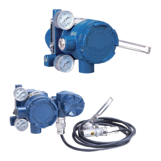
- Page 1 CM2-AVP300-2001 Smart Valve Positioner 300 Series Model AVP300/301/302 (Integral Type) 200 Series Model AVP200/201/202 (Remote Type) User's Manual...
- Page 2 • Please understand that we cannot in some cases accept responsibility for the results of use of this equipment by the customer. ® • HART is a trademark of FieldComm Group. ©1998–2017 Azbil Corporation All Rights Reserved.
- Page 3 Introduction ■ Thank you for purchasing an Azbil Corporation Smart Valve Positioner 200/300 Series. Smart Valve Positioner 200/300 Series (the devices) can be connected to a 4 to 20 mA signal line. Since all adjustments can be performed electrically using CommStaff, any desired relationship can be set between the input signal and the position of the control valve.
- Page 4 Safety precautions Symbols ■ These safety precautions are intended to help you to use the product safely and cor- rectly, and to prevent injury to yourself or others as well as damage to property. Be sure to follow all safety precautions. This manual makes use of a variety of symbols.
- Page 5 Introduction Cautions to ensure safe operation Warning Do not perform wiring work, turn on the electricity, etc., when your hands are wet. There is a risk of electric shock. Perform this work with the power supply turned off, and with dry or gloved hands. When wiring in a hazardous area, work according to the methods prescribed by the guidelines for the hazardous area.
- Page 6 Positioner Type Model AVP300/301/302 Model AVP200/201/202 (Integral Type) (Remote Type) Actuator Type Single-acting linear diaphragm (Azbil Corporation actuator model numbers: PSA, HA, HK, VA, VR, RSA, GOM) (See p. v.) (See p. xiii.) Double-acting linear cylinder (Azbil Corporation actuator model numbers: VP, SLOP, DAP) (See p.
- Page 7 Introduction Combination of model AVP300/301/302 (integral type) and single-acting linear diaphragm actuator 1. Attachment of feedback lever If the feedback lever alone cannot cover a full stroke, attach the extension lever to it. In order to minimize the risk of damage to the feedback lever...
- Page 8 90° Check the duty value of the electro-pneumatic module. in the UP direction (the DOWN direction for Azbil Cor- Regarding the confirmation method, see “EPM (electro- poration's VR and RSA actuators for VFR type control pneumatic module) operation confirmation procedure”...
- Page 9 Introduction Combination of model AVP300/301/302 (integral type) and double-acting linear cylinder actuator 1. Attachment of feedback lever Attach the extension lever securely, working from the front of the device, using the two included hexagon socket head bolts. In order to minimize the risk of damage to the feedback lever...
- Page 10 3. Air piping and electric wiring connection Check the span point and perform span adjustment. (1) Set the input signal to the span point (URV). (Zero ad- • Air piping connection justment can be performed if the input signal is adjusted (1) If control operation of control valve is direct operation to the zero point, and span adjustment can be performed This refers to the state in which the valve moves in the...
- Page 11 Introduction Combination of model AVP300/301/302 (integral type) and single-acting rotary cylinder actuator 1. Attachment of feedback lever In order to minimize the risk of damage to the feedback lever while it is carried or transported, and to minimize the pack- aging as well, the feedback lever is detached from the body of the device when it is packed.
- Page 12 Check the span point and perform span adjustment. (1) Set the input signal to the span point (URV). (Zero ad- justment can be performed if the input signal is adjusted to the zero point, and span adjustment can be performed if the input signal is adjusted to the span point.) (2) Using a flat-blade screwdriver, turn the external zero span adjustment switch on the upper part of the case in...
- Page 13 Introduction Combination of model AVP300/301/302 (integral type) and double-acting rotary cylinder actuator 1. Attachment of feedback lever In order to minimize the risk of damage to the feedback lever while it is carried or transported, and to minimize the pack- aging as well, the feedback lever is detached from the body of the device when it is packed.
- Page 14 4. Auto-setup 6. If suitable adjustment was not accomplished (1) Set the input signal to 18 ± 1 mA. [1] If auto-setup does not operate (2) Using a flat-blade screwdriver, turn the external zero/span • Check whether the input signal is 18 mA ± 1 mA. adjustment switch in the upper part of the case 90°...
- Page 15 Manufacturer Extension Lever Actuator Type Code PSA1, 2, PSK1 HA2, 3 VA1 to 3 PSA3, 4 PSA6 Azbil PSA7 Corporation VA4 to 6 RSA1 Attachment of Extension Lever and Feedback Lever RSA2 2. Attachment and installation VR2, 3...
- Page 16 UP (clockwise) direction (the DOWN direction for (See 5.2, “A/M Switch. ” ) Azbil Corporation's VR and RSA actuators for VFR type Supply air, and adjust the actuator air pressure such that the control valves), and hold that position for three seconds.
- Page 17 Introduction 6. If suitable adjustment was not accomplished [1] If auto-setup does not operate • Check whether the input signal is 18 mA ± 1 mA. • Check whether the A/M switch is set to automatic. If it is set to manual, switch it to auto. See 5.2, “A/M Switch, ” in this document for information on operating procedures.
- Page 18 Actuator Type Code [2] Positioner body configuration VP5, 6, 7 Install the body of the positioner onto the 2B stanchion. SLOP560, 1000, 1000X Azbil [3] Adjustment of attachment positions SLOP1500, 1500X Corporation DAP560, 1000, 1000X Procedure for adjustment of attachment positions...
- Page 19 Introduction 4. Auto-setup (1) Set the input signal to 18 ± 1 mA. (2) Using a flat-blade screwdriver, turn the external zero/ span adjustment switch in the upper part of the case 90° in the UP direction, and hold that position for three sec- onds.
- Page 20 6. If suitable adjustment was not accomplished [1] If auto-setup does not operate • Check whether the input signal is 18 mA ± 1 mA. • Check whether the A/M switch is set to automatic. If it is set to manual, switch it to auto. See 5.2, “A/M Switch, ” in this document for information on operating procedures.
- Page 21 Introduction Combination of model AVP200/201/202 (remote type) and single-acting rotary cylinder actuator 1. Attachment of feedback lever (pin) In order to minimize the risk of damage to the feedback lever while it is carried or transported, and to minimize the pack- aging as well, the feedback lever is detached from the valve travel detector when it is packed.
- Page 22 • Check whether the A/M switch is set to automatic. If it is in the UP direction (the DOWN direction for Azbil Cor- set to manual, switch it to auto. See 5.2, “A/M Switch, ” in poration's VR and RSA actuators for VFR type control this document for information on operating procedures.
- Page 23 Introduction Combination of model AVP200/201/202 (remote type) and double-acting rotary cylinder actuator 1. Attachment of feedback lever (pin) In order to minimize the risk of damage to the feedback lever while it is carried or transported, and to minimize the pack- aging as well, the feedback lever is detached from the valve travel detector when it is packed.
- Page 24 4. Auto-setup 6. If suitable adjustment was not accomplished (1) Set the input signal to 18 ±1 mA. [1] If auto-setup does not operate (2) Using a flat-blade screwdriver, turn the external zero/ • Check whether the input signal is 18 mA ± 1 mA. span adjustment switch in the upper part of the case 90°...
- Page 25 Introduction Product unpacking, verification, and storage Unpacking ■ This device is a precision instrument. Handle it carefully in order to prevent accidents, injuries, etc. Upon unpacking the product, verify that the following items are included. (When the device is shipped individually) •...
- Page 26 Storage ■ If the device that you have purchased is to be stored, please observe the following pre- cautions. • If storing the device unused 1. Store the device in the packed state in which it was shipped. 2. Store the device indoors in a low-vibration, low-shock area, and maintain normal indoor temperature and humidity (about 25 °C and 65 %).
-
Page 27: Table Of Contents
Contents Chapter 1: Control System Structure ���������������������������������������������������������������������������� 1-1 1.1 System Configuration ......................1-2 1.2 Travel Transmission Output (Models AVP301 and AVP201) ........1-3 1.2.1 Structure of system without travel transmission output ..........1.2.2 Structure of system with travel transmission (analog output) ........1.2.3 Structure of system with travel transmission (digital output) ........ - Page 28 Chapter 4: Communication-Based Operation ���������������������������������������������������������� 4-1 4.1 Starting Communication ....................4-2 Wiring method ..........................4.2 Communication-Based Operation ..................4-3 Menu Tree ............................4.3 Operation Data Confirmation ................... 4-7 4.3.1 Measured value confirmation ..................4.3.2 Adjustment data confirmation ..................4.4 Device Configuration and Adjustment ................4-8 4.4.1 Auto-setup .........................
- Page 29 Chapter 5: Maintenance and Troubleshooting ��������������������������������������������������������� 5-1 5.1 Troubleshooting ........................5-2 Types of problems .......................... Troubleshooting ..........................5.2 A/M Switch ........................... 5-6 5.3 Filter Replacement and Restriction Maintenance ............5-8 Filter replacement and restriction maintenance methods ............5.4 Cleaning the Flapper ......................5-9 5.5 Insulation Resistance Test ....................
- Page 31 Chapter 1: Control System Structure Overview of this chapter ■ This chapter describes the configuration of the control system used by this device. • The input/output system structure of the device is described. • The structure and the names and functions of the various parts of the device are described.
- Page 32 System Configuration This device is a smart valve positioner that can be connected to a 4 to 20 mA signal line from the output of a controller. Since all adjustments can be performed electrically, any desired relationship can be set between the input signal and the position of the control valve.
-
Page 33: Control System Structure
This figure shows the system structure of the device when the travel transmission func- tion is not used. 4–20 mA DC Host controller ® HART Communicator Main Unit (Models AVP302 and AVP202 only) or CommStaff CommStaff Figure 1-2. Structure of System without Output (Model AVP300, AVP302, AVP200, and AVP202) -
Page 34: Structure Of System With Travel Transmission (Analog Output)
1.2.2 Structure of system with travel transmission (analog output) This figure shows an example of the structure of a system in which the position detected by the device is output as a 4–20 mA DC analog signal. In this system structure, the analog signal from the device is directly output to the host monitoring system. -
Page 35: Description Of Device Structure And Functions
Chapter 1: Control System Structure Description of Device Structure and Functions The structure of the body of the device is shown below. Reversing relay Output air connection (OUT1) Body Output air pressure gauge External zero/span adjustment switch Mounting plate (optional) Feedback lever Terminal box cover... - Page 36 Each component is described in the following table. Name Description Main unit (also “Body”) • Houses the electronics module, EPM (electro-pneumatic module), and VTD (position sensor). Pilot relay • Amplifies the pneumatic signal from the EPM (electro-pneumatic module) and converts it to a pneumatic signal for the actuator. Feedback lever •...
-
Page 37: Terminal Box
Chapter 1: Control System Structure Terminal Box Houses an input signal (controller output) terminal, an output signal (travel transmis- sion) terminal, and an internal ground terminal. The structure of the terminal box is shown below. Figure 1-6. Structure of Terminal Box Figure 1-7. - Page 38 Output signal terminal • Labeled “I OUT. ” • Connect the signal cable for travel transmission. • This terminal screw is not present in model AVP300/302/200/202 (without travel transmission). External ground terminal • Ground this pin in accordance with the specifications.
-
Page 39: Chapter 2: Installation
Chapter 2: Installation Overview of this chapter ■ This chapter describes installation of the device and connection of its piping and wiring. Cautions to ensure safe operation Warning Do not perform wiring work, turn on the electricity, etc., when your hands are wet. There is a risk of electric shock. -
Page 40: Installation Location Selection Criteria
• Do not use a transceiver near the device. • Vibration of not more than 20 m/s (5 to 400 Hz) (model AVP300/301/302 and AVP200/201/202 main unit) • Vibration of not more than 100 m/s (5 to 2000 Hz) (model AVP200/201/202 valve... - Page 41 Chapter 2: Installation 2) End-installation type compressed air cleaner If fundamental measures cannot be taken on main lines due to problems related to, for example, control valve installation, install an end-installation type compressed air cleaner (oil mist removal equipment) and supply instrumentation air to the device through this compressed air cleaner.
-
Page 42: Installation Method
Installation Method 2.2.1 Attachment to actuator Smart valve positioners are designed for use in combination with a control valve that uses a linear or rotary actuator. The main unit weighs about 2.5 kg. It should be attached in the same manner as a conventional electro-pneumatic positioner. Caution •... - Page 43 Chapter 2: Installation Installation examples ■ Some typical installation examples are shown in the diagrams below. For actuators not appearing in the diagrams below, see the installation diagrams included with this device. [HA1 actuator] Lock nut Lock nut (with toothed washer) Hexagonal stud (with toothed washer) Hexagonal stud...
- Page 44 Installation procedure ■ The general installation procedure is shown below. Step Procedure Fasten the mounting plate securely to the rear of the positioner using the two hexagonal bolts (M8×20) and spring washers provided. Fasten the positioner (mounting plate) securely to the actuator's mounting structure using the bolts and washers provided.
-
Page 45: Air Piping Connection
Chapter 2: Installation (5) If attaching a rotary cylinder, attach it so that the rotary cylinder shaft comes be- tween the feedback pin and the device. Figure 2-5. Connection of Remote Type and Rotary Cylinder’s Feedback Pin and Feedback Lever Rear maintenance space ■... - Page 46 Supply air ■ • The supply air must be clean, dry air without moisture, oil, contaminants, or for- eign matter such as dust. In the air supply system, an aftercooler, air drier, filter, and the like should be installed after the compressor. Exercise caution with regard to, for example, the supply piping structure.
- Page 47 Chapter 2: Installation Connection position ■ The respective positions of the air supply connection and the output connection are shown in the diagram below. The dimensions of the screws for the connections can be selected based on the specifications. Figure 2-7. Air Piping Connection Note When connecting a solenoid valve, air valve, or the like for emergency cutoff, install it between the air output connection and actuator, and not on the supply air connection...
-
Page 48: Handling Of Double-Acting Reversing Relay
2.2.3 Handling of double-acting reversing relay A reversing relay is used when a double-acting actuator is used. What is a reversing relay? ■ The pressure (POUT2) of the reversing relay’s output air (OUT2) is expressed in the fol- lowing formula. OUT2 = P −... - Page 49 Chapter 2: Installation Supply air pressure connection to reversing relay ■ Connect the pipe for supply air pressure to the reversing relay. Installing a model KZ03 pressure regulator with filter to the body of the device The model KZ03 pressure regulator with filter has two output air connections. Connect one of the output air connections on the model KZ03 to the supply air connection on the body of the device using the special-purpose metal fittings, and connect the gap be- tween other output air connection and the supply air connection (SUP) on the reversing...
-
Page 50: Electrical Wiring Connection
Piping procedure ■ The procedure for installing the air piping by which the device drives the actuator is shown below. Step Procedure Remove the dustproof plug on the air piping connection. Connect the pipe joint to the connection. Note • As much as possible use sealing tape rather than solid or liquid sealant. •... - Page 51 Chapter 2: Installation External ground terminal ■ To connect to the external ground terminal, put the cable terminal between the flat washers. Cable terminal Flat washer Flat washer Only type 300 at washers can be used. Figure 2-13. Connection to the external ground terminal Types of electrical wiring ■...
- Page 52 Systems that use a position signal (four-line connection) ■ Detach the terminal box cover, and wire as shown in the diagram below. Figure 2-15-1. Wiring for Systems Using a Position Signal Figure 2-15-2. Wiring for Systems Using a Position Signal (Four-Line Cable) (Two-Line Cable) •...
-
Page 53: Power Supply For Input Signal And Travel Transmission
Chapter 2: Installation 2.2.5 Power supply for input signal and travel transmission Input signal ■ The input signal to the device is 4 to 20 mA. In addition, this input signal is used as the power supply. Note • Do not allow a current of 24 mA DC or higher. •... -
Page 54: Cables (For Input Signal Or Travel Transmission)
2.2.6 Cables (for input signal or travel transmission) Cable selection and conditions ■ The selection of and conditions related to cables for wiring are described below. • We recommend the use of CVV (JIS C 3401) 600 V control wires with PVC insulation and a conductor cross-section of 1.25 mm , or stranded cables with the same or better performance specifications. - Page 55 AVP300/301/200/201 except for intrinsically safe type is equivalent to 300 Ω), and the voltage between the terminals must be at least 8 V. Model AVP300/301 intrinsically safe type is equivalent to 350 Ω, and the voltage must be at least 7 V. Check the allowable load resistance and output voltage of the controller before use.
-
Page 56: Remote Type Handling
Remote Type Handling 2.3.1 Remote type cable handling Detaching the positioner body and cable ■ Step Procedure Remove the cover of terminal box on the body of the positioner. Remove the five terminals connected to the remote cable. Remove the watertight gland or flameproof cable gland that is attached to the terminal box on the body of the positioner. - Page 57 Chapter 2: Installation Adjusting length of remote cable ■ Step Procedure Remove the remote cable from the terminal box, and then cut a remote cable of a suitable length. Strip off about 6 cm of the sheath from the end of the cable, and strip off about 5 mm of the insulation of the wire.
-
Page 58: Attachment To The Actuator Of The Valve Travel Detector
2.3.2 Attachment to the actuator of the valve travel detector Changing direction of feedback lever (optional) ■ Change the orientation of the feedback lever in accordance with the cable wiring orien- tation, the constraints of the mounting bracket, etc. (1) Remove the lever (small) fixed to the position sensor shaft by removing the hex- agonal bolt. -
Page 59: Positioner Body Installation
The cable between the remote type valve travel detector and the body of the device can be cut to any desired length and then adjusted. Cable length adjustment must be performed by trained service personnel from Azbil Corporation, using special-purpose tools. If cable length adjustment is to be performed, be sure to consult with Azbil Corporation. -
Page 60: Flameproof Cable Gland And Explosion-Proof Universal Elbow
Flameproof Cable Gland and Explosion-proof Universal Elbow Introduction ■ If the TIIS flameproof model has been purchased, it will be delivered with the flame- proof cable gland included. The flameproof cable gland is used to seal the end of the cable, ensuring explosion- proof performance and improving insulation performance and mechanical strength. - Page 61 Chapter 2: Installation Structure of flameproof cable gland for use at 200 series main ■ part A full view and exploded view of the flameproof cable gland are shown below. Figure 2-24. Flameproof Cable Gland Full View Figure 2-25. Flameproof Cable Gland Exploded View 2-23...
- Page 62 Structure of explosion-proof universal elbow ■ The structure of the explosion-proof universal elbow is shown below. Figure 2-26. Explosion-proof Elbow Structure Installation examples ■ The flameproof cable gland and flameproof elbow are mounted on the conduit connec- tion of the terminal box, as shown in the diagrams below. [If the flameproof cable gland is used] [If the explosion-proof universal elbow is also used] Figure 2-27.
- Page 63 Chapter 2: Installation Flameproof cable gland installation procedure for AVP300 ■ The procedure for mounting the flameproof cable gland is shown below. Step Procedure Firmly tighten the entry body on the connection port and the universal elbow to hold it in place.
- Page 64 Flameproof cable gland installation procedure for use at 200 ■ series main part The flameproof cable gland installation procedure is shown below. Step Procedure Securely fasten the body to the terminal box connection or the universal elbow connection. Note • Apply adequate waterproofing to these parts. We recommend the use of silicone resin based non-hardening sealant materials.
- Page 65 Chapter 2: Installation Flameproof universal elbow installation procedure ■ The installation procedure for the flameproof universal elbow is shown below. Step Procedure Referring to the diagram below, position the lock nut so that its edge is aligned with the edge of the groove for the O-ring. Figure 2-28.
- Page 66 2-28...
-
Page 67: Chapter 3: Operation
Chapter 3: Operation Overview of this chapter ■ This chapter describes starting and stopping the device, as well as zero/span adjustment. If you have purchased this device separately, be sure to read Chapter 2, “Installation, ” before reading this chapter. Cautions to ensure safe operation Warning Do not perform wiring work, turn on the electricity, etc., when your hands are wet. -
Page 68: Auto-Setup
Auto-setup Before using this device, run auto-setup. After that, if necessary adjust the fully closed position (zero) and fully open position (span) that delineate valve travel. The device’s zero/span adjustment function electrically sets the valve closed and open positions independently, and is thus capable of performing this adjustment without mu- tual interference. -
Page 69: Overview Of Auto-Setup
Chapter 3: Operation 3.1.1 Overview of auto-setup Use this procedure to automatically set the following items. (1) Zero/span adjustment (However, by default the span point is set so that the overstroke becomes 10 %. If a span adjustment is done after auto-setup, the device changes and saves the over- stroke setting.) (2) Configuration of actuator operation (3) Configuration of the LRV (lower range value, the input signal at 0 %) and URV... - Page 70 Table 3-2. Remote Type settings Setting Direction Lever Lever Valve Valve travel Valve Control Action Actuator Valve position Position Movement direction Action Action Direct Reverse Reverse (Closed: 20 mA; open: 4 mA) Up → Down Closed → Open Reverse Direct Reverse (Closed: 4 mA;...
-
Page 71: Auto-Setup Operation
• In some cases, configuration may not succeed due to the actuator’s diaphragm capac- ity (if lower than with Azbil Corporation’s HA1 type actuator, which has a diaphragm capacity of 850 cm ) or operation stroke (if less than 14.3 mm). If this occurs, refer to 4.4.4, “Control parameter configuration, ”... -
Page 72: Zero/Span Adjustment
Zero/Span Adjustment The zero/span adjustment method that uses an external zero/span adjusting mechanism will now be described. [Adjustment Method] The zero/span adjustment screw functions as an on/off switch. When rotated 90° clock- wise, the UP switch turns on, when rotated 90° counterclockwise, the DOWN switch turns on, and when returned to the original position, both switches turn off. -
Page 73: Procedure To Adjust Valve To Fully Closed Position (Zero Point)
Chapter 3: Operation 3.2.1 Procedure to adjust valve to fully closed position (zero point) The procedure to adjust the valve to the fully closed position (zero point) is shown below. Step Procedure Input from a controller (constant-current supply) the preset electric current in the amount that corresponds to the valve being fully closed. -
Page 74: Starting Operation
Starting Operation 3.3.1 Pre-operation confirmation Confirmation procedures ■ The configuration data confirmation procedure is shown below. Check the following before starting operation. • The device is installed appropriately, and there is no damage or breakage to the feedback lever, feedback pin, etc. •... - Page 75 EPM balance adjustment is necessary. If EPM balance adjustment is not performed appropriately, the valve position may vary suddenly and damage the EPM, so be sure to have this adjustment carried out by Azbil Corporation service personnel, or by a representative who has received Azbil Corporation training.
-
Page 76: Stopping Operation
3.3.2 Starting operation Introduction ■ This device and the control valve form a manipulator which is used in process control. Always take adequate safety precautions when starting to operate the control valve using this device. Note If an explosion-proof device model is used in a hazardous area, pay particular attention to how well electrical wiring connections (adapters, blind caps, etc.), covers, and the like are tightened down. -
Page 77: Chapter 4: Communication-Based Operation
Chapter 4: Communication- Based Operation Overview of this chapter ■ This chapter describes operations that are performed using communication. Refer to this chapter for information regarding the basics of operations, the relationship between modes and data settings, data setting and modification, the saving of various types of data, etc. -
Page 78: Starting Communication
Introduction ■ The wiring method for communicating with this device will now be described. ® • With HART communication ® Figure 4-1. Wiring of HART Communication Tool (Model AVP302) • With SFN communication Figure 4-2. Wiring with CommStaff (Model AVP300/302) -
Page 79: Communication-Based Operation
Chapter 4: Communication-Based Operation Figure 4-3. Using the Travel Transmission Function (Model AVP301/201) Communication-Based Operation Operations such as adjustment and configuration of the device and reading on the device will now be described with reference to the menus of the CommStaff CFS100 model field communication software. -
Page 80: Menu Tree
Menu Tree... - Page 81 Chapter 4: Communication-Based Operation ® *1. Not displayed on the HART version. *2. Not displayed on the SFN version. *3. Not displayed when DE communication selected. *4. Enabled when DE communication selected (not shown). *5. Displayed when “Actuator Size” is “Param0. ” *6. Displayed when “Flow Type” is “User-defined. ”...
- Page 82 Versions ■ This chapter describes the functions of the following versions. [Model AVP300/301/200/201] Azbil software version: 3.5 or later [Model AVP302/202] ® HART Version 6 Device revision: 1 Software revision: 1 or later Azbil software version: 6.1 or later...
-
Page 83: Operation Data Confirmation
Chapter 4: Communication-Based Operation Operation Data Confirmation Allows confirmation of measured values and adjustment data for the operating state of the device. The following items can be checked. 4.3.1 Measured value confirmation Select [Process Variables]. You will be able to check the following items. (1) Input (mA) Displays the electric current input value. -
Page 84: Device Configuration And Adjustment
Device Configuration and Adjustment In device configuration and adjustment, the configuration and adjustment that are nec- ® essary for this device to operate properly are performed. For the HART version, first set the mode of the device to “Out of service. ” Select [Device] >>... -
Page 85: Zero/Span Adjustment
Chapter 4: Communication-Based Operation 4.4.2 Zero/span adjustment [Valve fully closed position configuration] The procedure for setting the valve fully closed position is shown below. Step Procedure Select [Device] >> [Setup] >> [Zero/Span Adjustment] >> [Angle Adjustment] >> [Zero]. Input the input signal that is to fully close the valve. If the forced fully closed setting (travel cutoff low) is 0 % (default value + 0.5 %) or higher, the screen for configuring the travel cutoff low will appear. -
Page 86: Valve System
[Reverse]. Note • Modifying the positioner action requires EPM (electro-pneumatic module) recon- figuration. Reconfiguration should be performed by an Azbil Corp. service repre- sentative. The procedure for configuring positioner action is shown below. Step Procedure Select [Device] >>... -
Page 87: Control Configuration
VR3, VR3H 5,800 PARAM 0 — — Set individually* * Consult with Azbil Corporation service personnel. Actuator size configuration procedure ■ Step Procedure Select [Device] >> [Setup] >> [Control Configuration] >> [Act. Size/Gland Packing Type], and check the current setting. - Page 88 Gland packing type configuration procedure ■ Step Procedure Select [Device] >> [Setup] >> [Control Configuration] >> [Act. Size/Gland Packing Type], and check the current setting. If the actuator size is 0, A, B, or C, the gland packing type is not displayed. Select [Device] >>...
-
Page 89: Input Range
Chapter 4: Communication-Based Operation 4.4.5 Input range This procedure sets the electric current input value when the valve is fully closed (LRV) and the electric current input value when the valve is fully open (URV). Values can be entered in the 4 to 20 mA range. A split range can be specified as well. Note •... -
Page 90: Flow Type
4.4.6 Flow Type Flow Type ■ This function sets, from among four types of flow rate characteristics, the relationship between the input signal and the position. A sketch of the four characteristics (linear, equal percent, quick open, and user-defined) is shown below. Figure 4-4. -
Page 91: Travel Cutoff
Chapter 4: Communication-Based Operation 4.4.7 Travel Cutoff Travel Cutoff ■ Sets the input signal values (%) that force the valve fully open and fully closed. The valve will be fully closed at input values less than the forced fully closed value, and will be fully open at input values greater than the forced fully open value. -
Page 92: Device Information Confirmation And Modification
Select [Device] >> [Device Information] >> [ID]. You will be able to check or modify the following items. (1) Manufacturer Displays the manufacturer of the device. “Azbil Corporation” is displayed. (2) Model Displays the name and model number of the device. “SVP-V2” is displayed. -
Page 93: Device Software Revision Information Confirmation
Displays the revision number of the software in the same device revision. (4) Azbil Software Version Displays the software revision number. This is Azbil Corporation’s internal man- agement number, and has a one-to-one correspondence with the software revision above. -
Page 94: Maintenance
Maintenance 4.6.1 Mode ® The HART version has two modes. One is “In service” and the other is “Out of service. ” When performing calibration or adjustment, or when changing settings, the control valve will move, so first verify that these operations will not result in problems that could adversely affect plant operation. -
Page 95: Dummy Input Signal
Chapter 4: Communication-Based Operation 4.6.3 Dummy input signal Sets the input signal via communication, regardless of the value of the input signal from the controller. This function can be effective when, for instance, isolating problems during troubleshooting. For example, if the control valve does not move in response to input signals from the controller, but the valve operates correctly in response to the simulated current input, it follows that the problem is somewhere between the wiring and the host system. -
Page 96: Save Current Settings
4.6.5 Save Current Settings Saves all of the device’s internal data (settings) in place of the factory shipment data specifications (the data that was set based on the model number). Use the “Load saved settings” operation to retrieve the saved data. We recommend saving the configuration data after the device has been installed and all configuration has been completed. -
Page 97: Valve Diagnostic Parameter Configuration
Chapter 4: Communication-Based Operation Valve Diagnostic Parameter Configuration Performs configuration necessary for valve diagnostics. 4.7.1 Stick-Slip A stick-slip value quantitatively represents abnormal valve movements caused by adhe- sion, seizing, and the like. Select [Diagnostics] >> [Valve Diagnostic Information] >> [Stick Slip]. You will be able to check or modify the following items. To change a value, select the item and then change it. -
Page 98: Total Stroke
4.7.2 Total Stroke This value is the result of totaling the distances (%, mm) that the valve moved. Select [Diagnostics] >> [Valve Diagnostic Information] >> [Total Stroke]. You will be able to check or modify the following items. To change a value, select the item and then change it. -
Page 99: Travel Histogram
Chapter 4: Communication-Based Operation 4.7.4 Travel Histogram Indicates how frequently the valve travels in the specified position ranges, as a propor- tion of the total travel time. [Travel Histogram] Select [Diagnostics] >> [Valve Diagnostic Information] >> [Travel Histogram] >> [Travel Histogram]. You will be able to check the following items. Travel Histogram 1 to Travel Histogram 16 ■... -
Page 100: Shut-Off Count
4.7.6 Shut-Off Count Counts the total number of times that the valve is fully closed. Select [Diagnostics] >> [Valve Diagnostic Information] >> [Shut-Off Count]. You will be able to check or modify the following items. To change a value, select the item and then change it. -
Page 101: Deviation Alarm
Chapter 4: Communication-Based Operation 4.7.8 Deviation Alarm Select [Diagnostics] >> [Valve Diagnostic Information] >> [Deviation Alarm]. You will be able to check or modify the following items. Deviation ■ Displays the position deviation value. Deviation Threshold +, Deviation Threshold − ■... -
Page 102: Self-Diagnostics
Self-diagnostics This device provides a self-diagnostics function. This is useful for troubleshooting. For information regarding measures to take in response to each message, see Chapter 5, “Troubleshooting. ” 4.8.1 Critical Failure Select [Diagnostics] >> [Positioner Diagnostic Status]. You will be able to check the sta- tus conditions shown below. -
Page 103: Valve Diagnostic Status
Chapter 4: Communication-Based Operation 4.8.3 Valve Diagnostic Status Select [Diagnostics] >> [Valve Diagnostic Status]. You will be able to check the status conditions shown below. If the value of an item is ON, an alarm was triggered. Status Details Stick Slip Alarm The Stick Slip Alarm occurs when the valve exhibits stick and slip movement. -
Page 104: Precautions
Precautions A message like the one below may be displayed on a host device. If so, take the indicated countermeasure to address the problem. [475 Communicator] • If Actuator Size is set to “Param0” and GE (+/−) in “PID Parameters” is set to any value other than “0.0, ”... - Page 105 Chapter 5: Maintenance and Troubleshooting Overview of this chapter ■ This chapter describes the maintenance of this device and countermeasures to take when problems occur. Cautions to ensure safe operation Warning Do not perform wiring work, turn on the electricity, etc., when your hands are wet. There is a risk of electric shock.
- Page 106 Troubleshooting Types of problems Introduction ■ The following three types of problems can conceivably occur when starting up and be- ginning to operate the device. • Problems due to a mismatch between device specifications and actual usage conditions • Problems due to erroneous configuration or operation •...
-
Page 107: Maintenance And Troubleshooting
Chapter 5: Maintenance and Troubleshooting Troubleshooting Introduction ■ Follow the procedures below to address any problems that occur during start-up or during operation. If these troubleshooting procedures do not fix the problem, there is a chance that the device is broken. Please use the contact information that appears on the back cover of this manual. - Page 108 4. Does the relationship between the power supply voltage and the external load satisfy the specifications? 5. Has wiring been carried out correctly for the respective models for which the travel transmission function is not included (models AVP300/302 and AVP200/202) and for which the travel transmission function is included (models AVP301 and AVP201)? 6.
-
Page 109: Troubleshooting
RAM electrical part failure There is a problem with the electrical RAM FAULT components. Contact the nearest Azbil Corporation branch office or sales office. ROM electrical part failure There is a problem with the electrical ROM FAULT components. -
Page 110: A/M Switch
A/M Switch Introduction ■ The A/M switch changes the control method for the output air from the positioner be- tween automatic operation and manual operation. Automatic operation ■ The output air pressure corresponding to the input signal is output from the device. Manual operation ■... - Page 111 Chapter 5: Maintenance and Troubleshooting Procedure for switching from automatic to manual operation ■ The procedure for switching from automatic operation to manual operation is shown below. Step Procedure Open the A/M switch cover plate by manually rotating it clockwise 180°. (The cover plate can be made to rotate easily by pressing on the upper left of the cover plate at the same time.) Rotate the A/M switch one turn in the counterclockwise direction (the MAN direction)
-
Page 112: Filter Replacement And Restriction Maintenance
Filter Replacement and Restriction Maintenance Filter replacement and restriction maintenance methods Introduction ■ Contamination from the instrumentation air that collect in the restriction unit of the device can be removed during maintenance. For the instrumentation air, use dry air which has been cleared of solid particles up to 3 µm in size (or less). Be sure to use a Phillips head screwdriver for the procedure below. -
Page 113: Cleaning The Flapper
Chapter 5: Maintenance and Troubleshooting Cleaning the Flapper Introduction ■ If contaminants from the instrumentation air have accumulated on the flapper, clean the flapper as described below. Step Procedure Remove the three pilot cover screws. Have scraps of paper 0.2 mm thick ready. Common business cards would be suitable. Use the scraps of paper to clean the contaminants that have accumulated in the gap between the EPM nozzle and the flapper. -
Page 114: Adjustment Procedure When Using Device With Booster Relay
Adjustment Procedure when using device with Booster Relay When using the device with a booster relay, perform adjustment as follows. Start adjustment Connect the air piping between the device and the booster relay correctly. Mounting of device and booster relay on control valve Adjust sensitivity by manipulating the sensitivity adjustment throttle of Booster relay sensitivity the booster relay. -
Page 115: List Of Default Internal Data Values
Chapter 5: Maintenance and Troubleshooting List of Default Internal Data Values Item Contents Tag number XXXXXXXX Output format ANALOG XMTR Burnout (fail-safe) indication DOWN SCALE Actuator operation REVERSE Positioner action DIRECT Valve action DIRECT Actuator size PARAM 1 Hysteresis HEAVY 1.200 4.000 0.5000... -
Page 116: Internal Block Diagram And I/O Flow
Internal Block Diagram and I/O Flow Internal Block Diagram ■ Figure 5-2. Internal Block Diagram I/O Flow ■ Figure 5-3. I/O Flow 5-12... -
Page 117: Replacement Parts
Chapter 5: Maintenance and Troubleshooting Replacement Parts Recommended Name Part Number Quantity Replacement Cycle* (Years) Cover assembly (with locking screw and O-ring) 80377007-001 (standard finish) 80377007-002 (corrosion-resistant finish) 80377007-003 (silver finish) O-ring (cover) 80020935-845 Phillips head screw with spring washer (terminal screw) set 80277581-001 —... - Page 118 (temperature, humidity, vibration, air quality, etc.) and operation profile (frequency of operation, ON/OFF opera- tion, etc.). *2. If travel transmission available *3. If extension lever required *4. Have an Azbil Corp. service representative perform replacement of the VTD assembly or O-ring (under the terminal block). 5-14...
- Page 119 Chapter 5: Maintenance and Troubleshooting Reversing relay 9. Arm spring 1. Cover assembly 10. Hex socket head cap bolt with spring washer (M5) (with locking screw and O-ring) 2. O-ring (cover) 3. Phillips head screw with spring washer (terminal screw) set 34.
- Page 120 5-16...
- Page 121 Chapter 6: Cautions Regarding Explosion-proof Models Cautions to ensure safe operation Warning Do not perform wiring work, turn on the electricity, etc., when your hands are wet. There is a risk of electric shock. Perform this work with the power supply turned off, and with dry or gloved hands.
-
Page 122: Cautions Regarding Explosion-Proof Models
Cautions regarding explosion-proof models Introduction ■ When using an explosion-proof model, be sure to use the product correctly, paying suf- ficient attention to the cautions in this chapter. Flameproof structure ■ “Flameproof structure” refers to a structure in which, if an explosion of the explosive gas occurs inside the enclosure in the fully closed state, the enclosure will withstand the resulting pressure, and in addition, there will be no danger of igniting external explosive gas. - Page 123 Chapter 6: Cautions regarding Explosion-Proof Models [2. FM Explosion-proof] Select an installation location for an FM explosion-proof model AVP in accordance with the following criteria. • Hazardous areas in which this device can be installed are defined as follows. [Explosion-proof] Class I, Division 1, Group A, B, C, and D For gas Ambient atmosphere of acetylene, ethylene, propane, etc.
- Page 124 Installation of an Explosion-proof or Dust-ignition-proof Apparatus (reproduced from the NEC) CAUTIONS • Install the apparatus only in hazardous (classified) locations for which the apparatus has been approved. • The sealing must be a maximum distance of 18 in. (457 mm) from the enclosure. •...
- Page 125 Chapter 6: Cautions regarding Explosion-Proof Models 3. Class II, Division 1 locations 3.1 Wiring methods • Threaded rigid metal conduit, threaded steel intermediate metal conduit, or Type MI cable with termina- tion fittings approved for the location, can be employed. 3.2 Sealing •...
- Page 126 [3. FM intrinsically safe] Select an installation location for an FM intrinsically safe model in accordance with the following criteria. • Hazardous areas in which this device can be installed are defined as follows. [Intrinsically safe] Class I, II, III, Division 1, Group A, B, C, D, E, F, G, T4 Gases with an ignition point of 135 °C or higher Gas and flammable dust Ambient atmosphere of acetylene, ethylene, propane, etc.;...
- Page 127 For models those date of manufacture are before September 2017 Input signal circuit: Model AVP300/301 12.02 ≤ V ≤ 30 V, I = 100 mA, Pi = 1 W, Ci = 0, Li = 0.22 mH Model AVP302 12.02 ≤...
- Page 128 [For models those date of manufacture are before September 2017]...
- Page 129 Chapter 6: Cautions regarding Explosion-Proof Models [For models those date of manufacture are before September 2017]...
- Page 130 [For models those date of manufacture are before September 2017] 6-10...
- Page 131 Chapter 6: Cautions regarding Explosion-Proof Models [For models those date of manufacture are before September 2017] 6-11...
- Page 132 [For models those date of manufacture are before September 2017] 6-12...
- Page 133 Chapter 6: Cautions regarding Explosion-Proof Models [For models those date of manufacture are after October 2017] 6-13...
- Page 134 [For models those date of manufacture are after October 2017] 6-14...
- Page 135 Chapter 6: Cautions regarding Explosion-Proof Models [For models those date of manufacture are after October 2017] 6-15...
- Page 136 [For models those date of manufacture are after October 2017] 6-16...
- Page 137 Chapter 6: Cautions regarding Explosion-Proof Models [For models those date of manufacture are after October 2017] 6-17...
- Page 138 [For models those date of manufacture are after October 2017] 6-18...
- Page 139 Chapter 6: Cautions regarding Explosion-Proof Models [For models those date of manufacture are after October 2017] 6-19...
- Page 140 [4. ATEX flameproof] ATEX Flameproof Certifications (English) 1. Marking information 0344 DEKRA 14ATEX0120 X II 2 G Ex db IIC T6 Gb -40°C Tamb +75°C IP66 2. Applicable standards - EN 60079-0: 2012 +A11 Electrical apparatus for explosive atmospheres - Part 0: General requirements - EN 60079-1: 2014 Electrical apparatus for explosive atmospheres –...
- Page 141 Chapter 6: Cautions regarding Explosion-Proof Models Certifications antidéflagrantes ATEX (français) 1. Informations de marquage 0344 DEKRA 14ATEX0120 X II 2 G Ex db IIC T6 Gb -40 °C Tamb +75 °C IP66 2. Normes applicables - EN 60079-0: 2012 +A11 Atmosphères explosives —...
- Page 142 ATEX Flammsicherheitsbescheinigung (Deutsch) 1. Kennzeichnungsinformationen 0344 DEKRA 14ATEX0120 X II 2 G Ex db IIC T6 Gb -40 °C Tamb +75 °C IP66 2. Gültige Normen - EN 60079-0: 2012 +A11 Explosionsgefährdete Bereiche — Teil 0: Betriebsmittel — Allgemeine Anforderungen - EN 60079-1: 2014 Explosionsfähige Atmosphäre —...
- Page 143 Chapter 6: Cautions regarding Explosion-Proof Models Certificazione antideflagrante ATEX (Italiano) 1. Informazioni marcatura 0344 DEKRA 14ATEX0120 X II 2 G Ex db IIC T6 Gb -40°C Tamb +75°C IP66 2. Standard applicabili - EN 60079-0: 2012 +A11 Apparecchiature elettriche per atmosfere esplosive - Parte 0: Requisiti generali - EN 60079-1: 2014 Apparecchiature elettriche per atmosfere esplosive –...
- Page 144 ATEX-certificering voor explosieveiligheid (Nederlands) 1. Informatie over markeringen 0344 DEKRA 14ATEX0120 X II 2 G Ex db IIC T6 Gb -40°C Tomg +75°C IP66 2. Geldende normen - EN 60079-0: 2012 +A11 Explosieve atmosferen — Deel 0: Elektrisch materieel — Algemene eisen - EN 60079-1: 2014 Explosieve atmosferen —...
- Page 145 Chapter 6: Cautions regarding Explosion-Proof Models ATEX Certificações de Antideflagrante (Português) 1. Informações de marcação 0344 DEKRA 14ATEX0120 X II 2 G Ex db IIC T6 Gb -40°C Tamb +75°C IP66 2. Normas aplicáveis - EN 60079-0: 2012 +A11 Atmosferas explosivas — Parte 0: Requisitos gerais - EN 60079-1: 2014 Atmosferas explosivas —...
- Page 146 Certificaciones ATEX a prueba de explosiones (español) 1. Información de marcado 0344 DEKRA 14ATEX0120 X II 2 G Ex db IIC T6 Gb -40 °C Tamb +75 °C IP66 2. Normas aplicables - EN 60079-0: 2012 +A11 Atmósferas explosivas. Parte 0: Equipo. Requisitos generales. - EN 60079-1: 2014 Atmósferas explosivas.
- Page 147 Input signal circuit: Model AVP300/301 Ui = 30 V, Ii = 100 mA, Pi = 1 W, Ci = 1 nF, Li = 0.2 mH Model AVP302 Ui = 30 V, Ii = 100 mA, Pi = 1 W, Ci = 26 nF, Li = 0.2 mH...
- Page 148 [6. NEPSI flameproof] Select an installation location for an NEPSI flameproof model in accordance with the following criteria. • Hazardous areas in which this device can be installed are defined as follows. [Zone 1 or 2 hazardous area] Ex d IIC T6 Gb; Ex tD A20 IP66 T85 °C Protection levels, classified based on the possibility that the device could be an ignition source Gases with an ignition point of 85 °C or higher...
- Page 149 Use the NEPSI intrinsic safety model device with a barrier that satisfies the specifica- tions below. For models those date of manufacture are before September 2017 Input signal circuit: Model AVP300/301/302 Ui = 30V, Ii = 95mA, Pi = 0.66W, Ci = 0, Li = 0.2mH Travel transmission circuit: Model AVP301 Ui = 30V, Ii = 95mA, Pi = 0.66W, Ci = 0, Li = 0.2mH...
- Page 150 Caution • When installing, operating, and maintaining the product, be sure to read this manual. In addition, observe the requirements in the following standards. GB50257-2014 “Code for construction and acceptance of electric device for explosion atmo- spheres and fire hazard electrical equipment installation engineering” GB3836.13-2013 “Explosive atmospheres - Part 13:Equipment repair,overhaul and reclama- tion”...
- Page 151 Chapter 6: Cautions regarding Explosion-Proof Models [8. IECEx flameproof] IECEx Flameproof Certifications 1. Marking information IECEx KEM 06.0015X Ex db IIC T6 Gb −40°C ≤ Tamb ≤ +75°C IP66 2. Applicable standards - IEC 60079-0: 2011 Electrical apparatus for explosive atmospheres - Part 0: General requirements - IEC 60079-1: 2014 Electrical apparatus for explosive atmospheres - Part1:...
- Page 152 Use the ATEX intrinsic safety explosion-proof model device with a barrier that satis- fies the specifications below. Input signal circuit: Model AVP300/301 Ui = 30 V, Ii = 100 mA, Pi = 1 W, Ci = 5 nF, Li = 0.22 mH Model AVP302 Ui = 30 V, Ii = 100 mA, Pi = 1 W, Ci = 41 nF, Li = 0.22 mH...
- Page 153 Chapter 6: Cautions regarding Explosion-Proof Models [10. INMETRO flameproof] Equipamento à prova de explosão do INMETRO Segurança Sobre este manual Este manual contém informações e advertências que devem ser observadas para manter posicionador de válvula smart o SVP3000 (SVP) que opera seguramente. Instalação correta, operação correta e manutenção regular são essenciais para assegurar segurança enquanto usando este dispositivo.
- Page 154 1. Marcação conforme a Portaria 179 do INMETRO: Azbil Corporation Tipo:AVP 300, 301, 302, 303, 304 e 331 Ex db IIC T6 Gb −40 °C ≤ Ta ≤ +75 °C Número de série: ... NCC 14.2783X ATENÇÃO – NÃO ABRA QUANDO UMA ATMOSFERA EXPLOSIVA PUDER ESTAR PRESENTE 2.
- Page 155 [11. EAC flameproof] Сертификация на соответствие техническому регламенту ТР ТС 012/2011 О безопасности оборудования для работы во взрывоопасных средах 1. Маркировка взрывозащищенных интеллектуальных электропневматических позиционеров клапанов SVP моделей AVP300, AVP301, AVP302. 2. Соответствуют: ГОСТ 30852.0-2002 (МЭК 60079-0:1998) ГОСТ 30852.1-2002 (МЭК 60079-1:1998) 3.
- Page 156 [12. EAC intrinsically safe] Сертификация на соответствие техническому регламенту ТР ТС 012/2011 О безопасности оборудования для работы во взрывоопасных средах 1. Маркировка искробезопасных интеллектуальных электропневматических позиционеров клапанов SVP моделей AVP300, AVP301, AVP302 2. Соответствуют: ГОСТ 30852.0-2002 (МЭК 60079-0: 1998) ГОСТ 30852.10-2002 (МЭК 60079-11: 1999) 3.
- Page 157 Chapter 6: Cautions regarding Explosion-Proof Models [13. CNS flameproof] CNS 防爆設備(耐壓) Ex d IIC T6 Gb X 1 : 防爆認證 2 : 隔爆 3 : 爆炸性氣體環境歸類為 IIC 4 : 著火點為 85 ℃或其以上的氣體環境 5 : 設備防護等級 基于机器有可能成为起火点而区分的保护级别 6 :...
- Page 158 X: 檢定範圍未包含電纜入口保護裝置,應正確使用合格電纜接頭或盲塞以維持 設備保護型式之完整性。 本設備鋁製外殼安裝於需 EPL Ga 區域使用時,應避免外殼碰撞或摩擦。 環境溫度 : -40 ℃ 至 +60 ℃ 防塵防水性能 : IP66 本機可設置的危險場所 : Zone 0, 1 或 2 的危險場所 請參閱以下電氣參數 AVP300 型 僅用於連接本質安全認證的電路 ; 數值如下 最大值 : 電 源 / 輸入電路 : Ui=30 V, Ii=100 mA, Pi=1 W, Ci=5 nF, Li=0.22 mH 監控 / 輸出電路 : Ui=10 V, Ii=100 mA, Pi=1 W, Ci=1 nF, Li=0.22 mH AVP301 型 僅用於連接到認證的本質安全認證的電路 ; 數值如下 最大值 : 電...
- Page 159 Chapter 6: Cautions regarding Explosion-Proof Models [15. KOSHA flameproof (Main unit model number “H”)] KOSHA Flameproof Marking information Ex d IIC T6 −40°C ≤ Tamb ≤ +75°C 13-AV4BO-0539 Instruction for safe use • It should be ensured that the supply wires are suitable for 5°C above surrounding atmospheres. •...
-
Page 160: Appendix A: Specifications
Appendix A: Specifications Appendix A: Specifications Model AVP300/301/302 (for models those date of manufacture are before September 2017) Azbil Corporation No. SS2-AVP300-0100 LIST OF FEATURES Item Function Desired input signal range Any split-range value can be specified. Forced fully open/closed The control valve can be fully closed or opened securely when the desired percentage of input signal is reached. - Page 161 No. SS2-AVP300-0100 Azbil Corporation Item Specification Performance Accuracy For 8 mA≤input signal span < 16 mA: ±1 %F.S. (±2.5 % with user-defined flow characteristics) For 4 mA≤input signal span < 8 mA: ±1.5 %F.S. (Refer to Table 1. Because accuracy varies depending on the combination of actuator size and travel.) Travel transmission ±1 %F.S.
- Page 162 Appendix A: Specifications Azbil Corporation No. SS2-AVP300-0100 Item Specification Approvals INMETRO Ex db IIC T6 Gb Flameproof Flameproof cable gland must be Ex db IIC approved. Note: IP66 waterproof and dust-proof performance can be assured by installing an appropriate cable gland.
- Page 163 Model AVP300/301/302 (for models those date of manufacture are after October 2017) LIST OF FEATURES Item Function Desired input signal range Any split-range value can be specified. Forced fully open/closed The control valve can be fully closed or opened securely when the desired percentage of input signal is reached.
- Page 164 The barriers should be ATEX certified types and comply with the following condition as follows: Input circuit (terminals ±IIN) Model AVP300/301: Ui=30 V, Ii=100 mA, Pi=1 W, Ci=1 nF, Li=0.2 mH Model AVP302: Ui=30 V, Ii=100 mA, Pi=1 W, Ci=26 nF, Li=0.2 mH Output circuit (terminals ±IOUT) Model AVP301: Ui=30 V, Ii=100 mA, Pi=1 W, Ci=3 nF, Li=0.2 mH...
- Page 165 EAC Intrinsically safe 0 Ex ia IIC T4 X IEC IP66 Input circuit (terminals ±IIN) Model AVP300/301: Ui=30 V, Ii=100 mA, Pi=1 W, Ci=1 nF, Li=0.2 mH Model AVP302: Ui=30 V, Ii=100 mA, Pi=1 W, Ci=26 nF, Li=0.2 mH Output circuit (terminals ±IOUT) Model AVP301: Ui=30 V, Ii=100 mA, Pi=1 W, Ci=3 nF, Li=0.2 mH...
- Page 166 Ambient humidity limits 10 to 90 %RH Vibration characteristics Body: 20 m/s , 5 to 400 Hz Valve travel detector: 100 m/s , 5 to 2000 Hz (with standard mounting kit on Azbil Corporation’s HA actuator) Finish Baked acrylic Color Dark blue...
- Page 167 Item Specification Weight Body: • For single acting actuator Without Pressure regulator with filter: 3.3 kg With Pressure regulator with filter: 4.0 kg • For double acting actuator:Without Pressure regulator with filter: 3.6 kg With Pressure regulator with filter: 4.3 kg Valve travel detector: 1.0 kg Cable: 0.2 kg/m Outer diameter: 9.8 mm...
- Page 168 (psi) *1. Model AVP300/302 includes one flameproof cable gland, and model AVP301 includes two. *2. When the input signal (power) is shut off, select direct action to make the output air pressure of this device zero, and reverse action to make the output at the maximum air pressure (supply air pressure).
- Page 169 Selection of input characterization The flow characteristic of a control valve is set by selecting the valve plug characteristic, and the input-output characteristics of the positioner must be specified as linear. However, if the valve plug flow characteristic, which depends on the control valve’s shape and structure, does not meet requirements, you can correct the overall flow characteristic of the control valve by specifying “equal percentage”...
- Page 170 Appendix A: Specifications Table 2. Mounting bracket for single acting actuator (8)(9) Mounting bracket for pneumatic actuator Code Motoyama Mfg. 2800 series 240, 280, 330, Nihon Koso A100 series 270, 320 * Motoyama Mfg. 2800 series 400, 500S, 500L, Nihon Koso A100 series 400, 500 * Motoyama Mfg.
- Page 171 Table 3. Mounting bracket for double acting actuator (8)(9) Mounting bracket for pneumatic actuator Code Pentair Valve and Control Japan AK09, AK12, AK15 Pentair Valve and Control Japan AG06, AGN06 Pentair Valve and Control Japan AG09, AGN09 Pentair Valve and Control Japan AG13, AGN13 Pentair Valve and Control Japan AW13 Pentair Valve and Control Japan AW17 Pentair Valve and Control Japan AW20...
- Page 172 Appendix A: Specifications Model Number Configuration Basic model number AVP200 Analog signal (4 to 20 mA DC) without travel transmission - (1) (2) (3) (4) (5) (6) (7) (8) (9) - (10) AVP201 Analog signal (4 to 20 mA DC) with travel transmission ®...
- Page 173 Accessory Selection (6) (7) (8) (9) - (10) Without regulator (6) Pressure regulator Model KZ03 pressure regulator with filter (Mounted on positioner) * with filter (7) Cable length 10 m 20 m No mounting plate Single-acting PSA1, PSA2, PSK1 actuators New model of PSA3, PSA4 / VA1 to VA3 produced after 2000 * Previous model of PSA3, PSA4 for existing valves produced on/before 1999 PSA6 / VA4 to VA6 produced after Apr.
- Page 174 Appendix A: Specifications Table 6. Mounting bracket for single acting actuator (8)(9) Mounting bracket for pneumatic actuator Code Motoyama Mfg. 2800 series 240, 280, 330, NIHON KOSO A100 series 270, 320 * Motoyama Mfg. 2800 series 400, 500S, 500L, NIHON KOSO A100 series 400, 500 * Motoyama Mfg.
- Page 175 Table 7. Mounting bracket for double acting actuator (8)(9) Mounting bracket for pneumatic actuator Code NIHON KOSO 6300 series 63A2, AT series AT20 * NIHON KOSO 6300 series 63A3, B2, BA, B3, BB, B5, AT series AT-30, 200, 250, 300, 350, 500 * NIHON KOSO 6300 series 63A4, A5, A6, AT series AT40, AT50, AT60 * NIHON KOSO 6300 series AT series AT25 * NIHON KOSO TC-500 series TC-520W *...
- Page 176 Appendix A: Specifications Dimensions (Model AVP300/301/302) [For single-acting actuator without KZ03 regulator] unit: mm With 40 mm extension lever 43.5 Attach such that, when (Output air the lever is horizonal, pressure connection) the connector pin is Lever deflection* within this range.
- Page 177 [For single-acting actuator with KZ03 regulator] unit: mm With 40 mm extension lever 43.5 Attach such that, when (Output air the lever is horizonal, pressure connection) the connector pin is Lever deflection* within this range. ±4° to ±20° 6 Connector pin With 40 mm extension lever *1.
- Page 178 Appendix A: Specifications [For double-acting actuator without KZ03 regulator] unit: mm (220) [For double-acting actuator with KZ03 regulator] unit: mm (270) A-19...
- Page 179 Dimensions (Model AVP200/201/202) [Single-Acting, without Pressure Regulator] unit: mm Output air connection Electrical wiring connection Supply air connection Supply air connection Auto/manual switch 2B pipe Electrical wiring connection Mounting bracket For rotary valve U bolts and nuts 92 to 122 ±4°...
- Page 180 Appendix A: Specifications [Single-Acting, with Pressure Regulator] unit: mm Output air connection Air set Electrical wiring connection *2 Supply Auto/manual switch air connection Electrical wiring connection 2B pipe Mounting bracket For rotary valve U bolts and nuts 92 to 122 ±4°...
- Page 181 [Double-Acting, with Pressure Regulator] unit: mm (270) Output air connection (OUT1) Air set Auto/manual switch Supply air connection Electrical wiring connection *1 Electrical 2B pipe wiring connection For rotary valve 92 to 122 Output air connection (OUT2) Mounting bracket ±4° to ±20° U bolts and nuts Explosion-proof model...
- Page 182 Appendix A: Specifications [Double-Acting, without Pressure Regulator] unit: mm (220) *1 Electrical wiring *2 Output air connection (OUT1) connection Auto/manual switch Supply air connection *1 Electrical wiring connection 2B pipe Mounting bracket *2 Output air connection (OUT2) For rotary valve 92 to 122 ±4°...
- Page 183 [For Rotary Valve Actuator] unit: mm Lever deflection angle ±4° to ±20° Note: In terms of mechanical operation, do not exceed ±30° U sable range 85 to 115 M6 or 1/4-20 UNC screw, depth 10 (2, opposite side) Stem clamp M6 or 1/4-20 UNC screw Explosion-proof model A-24...
- Page 184 Appendix A: Specifications A-25...
-
Page 186: Terms And Conditions
1. Warranty period and warranty scope 1.1 Warranty period Azbil Corporation's products shall be warranted for one (1) year from the date of your purchase of the said products or the delivery of the said products to a place designated by you. - Page 187 Although acceleration of the above situation varies depending on the conditions or environment of use of the products, you are required not to use any Azbil Corporation's products for a period exceeding ten (10) years unless otherwise stated in specifications or instruction manuals.
- Page 189 Document Number: CM2-AVP300-2001 Document Name: Smart Valve Positioner 300 Series: Model AVP300/301/302 (Integral Type) 200 Series: Model AVP200/201/202 (Remote Type) User's Manual Date: 1st edition: Oct. 1998 27th edition: Sep. 2017 Issued/Edited by: Azbil Corporation...
Need help?
Do you have a question about the AVP300 and is the answer not in the manual?
Questions and answers