Table of Contents
Advertisement
Quick Links
Advertisement
Table of Contents

Subscribe to Our Youtube Channel
Related Manuals for Azbil 100 Series


Summary of Contents for Azbil 100 Series
- Page 1 CM2-AVP100-2001 Smart Valve Positioner 100 Series Model AVP100/102 User's Manual...
- Page 2 In no event shall Azbil Corporation be liable to anyone for any indirect, special or consequential damages. This information and specifications in this document are subject to change without notice.
- Page 3 Safety Precautions for Use For safe use of the product, the following symbols are used in this manual. Warnings are indicated when mishandling the product might WARNING result in the death or serious injury of the user. Cautions are indicated when mishandling the product might CAUTION result in minor injury to the user or damage to property.
- Page 4 CAUTION After installation, do not step or stand on this unit. Doing so may damage the device or cause injury. Bumping the glass of the display with a tool may cause damage or injury. Be careful. Install the device correctly. Incorrect or incomplete installation will cause output errors and violation of regulations.
- Page 5 If you are storing your SVP after it has been used, clean the SVP thoroughly and then firmly tighten the terminal box cover and seal the wiring, piping connections and bleed hole on the pilot cover using Azbil Corporation-supplied caps or tape to prevent entry of moisture.
- Page 6 Approval NEPSI Intrinsically Safe Approval for Smart Valve Positioner Model AVP100/102 NEPSI 本安防爆 1. 防爆标志 Ex ia Ⅱ C T4~T6 Ga 2. 国家防爆标准 GB3836.1–2010 爆炸性环境 第 1 部分 : 设备 通用要求 GB3836.4–2010 爆炸性环境 第 4 部分 : 由本质安全型 “i” 保护的设备 GB3836.20–2010 爆炸性环境...
-
Page 7: Table Of Contents
Table of Contents Chapter 1. Introduction ............1-1 1-1. - Page 8 4-6. Maintenance ............... . 4-18 4-6-1.
-
Page 9: Chapter 1. Introduction
Integral type Model AVP100: Analog signal (4-20 mA DC) without travel transmission Model AVP102: Analog signal (4-20 mA DC) with HART communication protocol Actuator air Smart Valve Positioner 100 Series Commsta Model (CFS100) (for model AVP100/102) Filtered Air Supply Process... -
Page 10: Communication
4-20 mA analog signal (refer to ordered specifications) or analogous HART signal. 1-2-2. Using a Commstaff Azbil Corporation’s Commstaff Model (CFS100) can be used for all configuration, calibration and maintenance of the SVP. SVP-specific communicator functions are documented fully in this manual. -
Page 11: Svp Diagrams
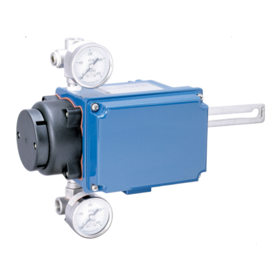
1-3. SVP diagrams Output air connection Pilot relay Output air pressure gauge (option) Zero/Span adjustment auto-setup switch Feedback lever Auto/Manual switch Input air pressure gauge (option) Cover Conduit conn. Main unit Air supply connection Fig. 1-3. SVP diagram... -
Page 13: Chapter 2. Installation
„ For HA Actuators, vibration cannot be more than 2G (5 to 400 Hz) Azbil Corporation’s Smart Valve Positioner 100 Series are designed for use in combination with a control valve that uses a direct- or reverse- acting or rotary actuator. The main SVP unit weighs about 1.7 kg. - Page 14 Before installing the SVP, check for: Use the appropriate mounting plate and feedback lever length for the Variations actuator. Do not install the SVP in such a place that it will be difficult to maintain or Clearance that will interfere with piping, wiring, or adjustment. Check for mechanical interference and valve operating clearance.
-
Page 15: Svp Assembly
2-1. SVP assembly 2-1-1. Attaching SVP feedback lever The SVP is factory shipped with the feedback lever removed. Follow the assembly procedures for the SVP and the feedback lever given below. Linear motion actuator „ Assemble the feedback lever and the SVP using the two provided hex socket bolts. „... - Page 16 Fig. 2-2. SVP maximum range motion Rotary motion actuator „ Place the coupling onto the angle sensor and fasten it with the bolt. „ Insert the spring pin into the hole in the coupling. „ Install the feed back lever so that the tip of the spring pin fits into the small hole on it to meed to the tip of the spring pin.
-
Page 17: Svp Installation Procedure
2-2. SVP Installation procedure The Smart Valve Positioner 100 Series can be attached onto a variety of actuators. Example actuator mountings are shown below. Please refer to the installation instructions that were included with your actuator mounting kit. Example1: How to mount the SVP onto a linear motion actuator. - Page 18 Example 2: How to mount the SVP to a rotary motion Actuator „ Attach the mounting bracket to the SVP securely using the provided hexagon head bolts (M6) and washers. „ Assemble the arm and the connector pin with a hexagon nut and a washer. „...
-
Page 19: Air Supply
2-3. Air supply Clean and dry supply air ensures long-term stability of the SVP. A typical air supply system is shown below: To actuator Air output connection 1/4NPT thread Auto/Manual Switch Regulator valve with lter Shuto valve Air supply Fig. 2-6. Air supply must be clean;... -
Page 20: Initial Svp Adjustment
2-4. Initial SVP adjustment WARNING Switching the SVP air supply from automatic to manual will divert air directly to the actuator, actuate the control valve and affect the process. Take the necessary precautions before turning the A/M switch. Valvetravel indicator at 50% travel Stem connector pin assembly... -
Page 21: Electrical Wiring
2-5. Electrical wiring The wiring terminals are located in the main unit of the SVP. Typical wiring from the control room to the SVP and possible way to connect a Commstaff or HART communicator are illustrated below. A Commstaff can be connected directly to the hooks. Apply sufficient waterproofing treatment using nonhardening sealants made of silicone resins. -
Page 22: Wiring Guidelines
2-5-2. Wiring procedure (1) Unscrew the screw on the cover and remove the cover. (2) Remove one or both of the supplied Azbil Corporation conduit connection blind plugs depending on how you plan to wire the SVP. (3) Insert cables into the conduit connection. Strip and attach the appropriate wires to the terminals, checking for polarity. -
Page 23: Svp For Springless Double-Acting Actuators (Reversing Relay)
2-6. SVP for springless double-acting actuators (Reversing relay) When an SVP is installed on a valve with a springless (double-acting) actuator, air pressure is needed on both the bottom and top of the actuator diaphragm to provide valve opening and closing proportional to a control signal. - Page 24 2-6-1. Installing the reversing relay on an SVP Remove the dust plug from the output air connection. Screw the Relay air connection of the reversing relay into the output air connection on the top of the SVP. Sealing tape is preferable to solid or liquid sealants for pipe joints to SVP air connections.
- Page 25 2-6-2. Double-acting SVP without air regulator directly attached Using a T-connector, connect the air supply from the regulator and filter to both the SVP Supply air connection and the Supply air connection on the reversing relay using sealing tape. Make sure to connect only one regulator to an SVP and reversing relay combination. Fig.
-
Page 26: Attaching Double-Acting Svp To A Diaphragm Actuator
2-6-3. Attaching double-acting SVP to a diaphragm actuator Reverse-acting actuator Connect OUT1 of the Reversing Relay to the bottom actuator air port Connect OUT2 of the Reversing Relay to the top actuator air port Direct-acting actuator Connect OUT1 of the Reversing Relay to the top actuator air port Connect OUT2 of the Reversing Relay to the bottom actuator air port 2-6-4. -
Page 27: Auto-Setup
2-6-5. Auto-setup Perform Auto-setup normally as per the instructions on page 3-1 through page 3-2 (perform the manual Zero-span adjustment on page 3-3 if necessary). When an SVP is attached to a rotary actuator, Zero and Span are sometimes set in reverse. Use a Commstaff to manually set the Actuator to the correct action (Direct or Reverse) as per the steps on page 4-10. - Page 28 2-16...
-
Page 29: Chapter 3. Adjustments
1%. If you didn’t specify the type of actuator, and you are using a non-Azbil Corporation actuator, then please refer to page 4-11 for instructions on how to enter the actuator type using a Commstaff. Tight shut-off requires the proper overtravel setting. -
Page 30: Auto-Setup Using The Travel Switch
In some cases, the auto-setup routine will not properly detect your valve, especially if the valve's actuator is smaller than Azbil Corporation's HA1 type actuator (diaphragm capacity of (850 cm {52 inches })) or the operation stroke is smaller than 14.3 mm... -
Page 31: Zero-Span Adjustment
3-2. Zero-span adjustment After Auto-setup, the SVP has calibrated itself to the fully shut (zero) and fully open (span) values of the valve. If the valve is not achieving the proper relationship between its travel and the control signal of the SVP, then please adjust Zero-span manually by following the steps below. - Page 32 communicator Fig. 3-2. Procedure for adjusting the fully opened valve position (span) Step Procedure From the controller or from a constant current supply, provide an input signal that corresponds to the valve fully opened (Example: 20 mA) Adjust the fully opened valve position by pushing the travel switch “UP” or “DOWN”...
-
Page 33: Chapter 4. Communication-Based Operation
Chapter 4. Communication-Based Operation Overview of this chapter This chapter describes operations that are performed using communication. Refer to this chapter for information regarding the basics of operations, the relationship between modes and data settings, data setting and modification, the saving of various types of data, etc. -
Page 34: Starting Communication
4-1. Starting Communication Before starting communication Confirm the following points before starting communication. „ Electrical wiring of the device is completed (see the “Wiring method” below). „ There is an input signal from the controller (constant-current supply). Note) If there is no 4 to 20 mA DC signal from the controller, connect a constant-current supply (3.85 to 21.5 mA DC) to the input signal terminal. -
Page 35: Communication-Based Operation
4-2. Communication-Based Operation Operations such as adjustment and configuration of the device and reading on the device will now be described with reference to the menus of the CommStaff CFS100 model field communication software. Regarding operating methods, see the CommStaff Smart Positioner Edition Operating Manual (No. - Page 36 4-2-1. Menu Tree...
- Page 37 Not displayed on the HART® version. Not displayed on the SFN version. Not displayed when DE communication selected. Enabled when DE communication selected (not shown). Displayed when “Actuator Size” is “Param0. ” Displayed when “Flow Type” is “User-defined. ”...
- Page 38 Versions This chapter describes the functions of the following versions. [Model AVP100] Azbil software version: 3.5 or later [Model AVP102] HART® Version 6 Device revision: 1 Software revision: 1 or later Azbil software version: 6.1 or later...
-
Page 39: Operation Data Confirmation
4-3. Operation Data Confirmation Allows confirmation of measured values and adjustment data for the operating state of the device. The following items can be checked. 4-3-1. Measured value confirmation Select [Process Variables]. You will be able to check the following items. (1) Input (mA) Displays the electric current input value. -
Page 40: Device Configuration And Adjustment
4-4. Device Configuration and Adjustment In device configuration and adjustment, the configuration and adjustment that are necessary for this device to operate properly are performed. For the HART® version, first set the mode of the device to “Out of service. ” Select [Device] >>... -
Page 41: Zero/Span Adjustment
4-4-2. Zero/span adjustment [Valve fully closed position configuration] The procedure for setting the valve fully closed position is shown below. step Procedure Select [Device] >> [Setup] >> [Zero/Span Adjustment] >> [Angle Adjustment] >> [Zero]. Input the input signal that is to fully close the valve. If the forced fully closed setting (travel cutoff low) is 0 % (default value + 0.5 %) or higher, the screen for configuring the travel cutoff low will appear. -
Page 42: Valve System
[Direct]; to make the output air pressure go to the maximum level, set this to [Reverse]. Note) Modif ying the positioner action requires EPM (electro-pneumatic module) reconfiguration. Reconfiguration should be performed by an Azbil Corp. service representative. The procedure for configuring positioner action is shown below. -
Page 43: Control Configuration
Size], and select from parameters 0 to 9, A, B, and C. If parameter 0 has been selected, the gap action type PID parameters can be set individually. (Parameters 7 to 9 are specifically for the Azbil Corporation VFR control valve RSA/VR actuator.) - Page 44 Gland packing type For the hysteresis difference due to friction of the control valve gland packing, select from [Heavy], [Medium] and [Light]. (This is selected automatically when autosetup is executed.) Regarding the types of gland packing, see Table 4-2 below. Table 4-2.
-
Page 45: Input Range
Gap PID parameter configuration procedure step Procedure Select [Device] >> [Setup] >> [Control Configuration] >> [Change Actuator Size], and set the actuator size to the parameter 0. The PID parameters will be displayed. Select [Device] >> [Setup] >> [Control Configuration] >> [PID Parameter]. You will be able to check or modify seven PID parameters (P, I, D, GE, GP, GI, and GD). -
Page 46: Flow Type
4-4-6. Flow Type This function sets, from among four types of flow rate characteristics, the relationship between the input signal and the position. A sketch of the four characteristics (linear, equal percent, quick open, and user-defined) is shown below. Fig. 4-3. Flow Characteristics Overview Note) If this has been set to user-defined, the flow rate characteristics conversion data can (must) be specified. -
Page 47: Travel Cutoff
4-4-7. Travel Cutoff Sets the input signal values (%) that force the valve fully open and fully closed. The valve will be fully closed at input values less than the forced fully closed value, and will be fully open at input values greater than the forced fully open value. -
Page 48: Device Information Confirmation And Modification
Select [Device] >> [Device Information] >> [ID]. You will be able to check or modify the following items. (1) Manufacturer Displays the manufacturer of the device. “Azbil Corporation” is displayed. (2) Model Displays the name and model number of the device. “SVP-V2” is displayed. -
Page 49: Device Software Revision Information Confirmation
(3) Software Revision (HART® version only) Displays the revision number of the software in the same device revision. (4) Azbil Software Version Displays the software revision number. This is Azbil Corporation’s internal management number, and has a one-to-one correspondence with the software revision above. 4-17... -
Page 50: Maintenance
4-6. Maintenance 4-6-1. Mode The HART® version has two modes. One is “In service” and the other is “Out of service. ” When performing calibration or adjustment, or when changing settings, the control valve will move, so first verify that these operations will not result in problems that could adversely affect plant operation. -
Page 51: Dummy Input Signal
4-6-3. Dummy input signal Sets the input signal via communication, regardless of the value of the input signal from the controller. This function can be effective when, for instance, isolating problems during troubleshooting. For example, if the control valve does not move in response to input signals from the controller, but the valve operates correctly in response to the simulated current input, it follows that the problem is somewhere between the wiring and the host system. -
Page 52: Save Current Settings
4-6-5. Save Current Settings Saves all of the device’s internal data (settings) in place of the factory shipment data specifications (the data that was set based on the model number). Use the “Load saved settings” operation to retrieve the saved data. We recommend saving the configuration data after the device has been installed and all configuration has been completed. -
Page 53: Valve Diagnostic Parameter Configuration
4-7. Valve Diagnostic Parameter Configuration Performs configuration necessary for valve diagnostics. 4-7-1. Stick-Slip A stick-slip value quantitatively represents abnormal valve movements caused by adhesion, seizing, and the like. Select [Diagnostics] >> [Valve Diagnostic Information] >> [Stick Slip]. You will be able to check or modify the following items. To change a value, select the item and then change it. -
Page 54: Total Stroke
4-7-2. Total Stroke This value is the result of totaling the distances (%, mm) that the valve moved. Select [Diagnostics] >> [Valve Diagnostic Information] >> [Total Stroke]. You will be able to check or modify the following items. To change a value, select the item and then change it. Total Stroke Displays and allows modification of the total stroke value. -
Page 55: Travel Histogram
4-7-4. Travel Histogram Indicates how frequently the valve travels in the specified position ranges, as a proportion of the total travel time. [Travel Histogram] Select [Diagnostics] >> [Valve Diagnostic Information] >> [Travel Histogram] >> [Travel Histogram]. You will be able to check the following items. Travel Histogram 1 to Travel Histogram 16 Displays the frequency of the specified position region as a percentage. -
Page 56: Shut-Off Count
4-7-6. Shut-Off Count Counts the total number of times that the valve is fully closed. Select [Diagnostics] >> [Valve Diagnostic Information] >> [Shut-Off Count]. You will be able to check or modify the following items. To change a value, select the item and then change it. Shut-Off Count Displays and allows modification of the total fully closed count. -
Page 57: Deviation Alarm
4-7-8. Deviation Alarm Select [Diagnostics] >> [Valve Diagnostic Information] >> [Deviation Alarm]. You will be able to check or modify the following items. Deviation Displays the position deviation value. Deviation Threshold +, Deviation Threshold − Displays and allows modification of the thresholds on the “+” side and “−” side. An alarm occurs if the position deviation exceeds this value. -
Page 58: Self-Diagnostics
4-8. Self-diagnostics This device provides a self-diagnostics function. This is useful for troubleshooting. For information regarding measures to take in response to each message, see “6-1. Troubleshooting. ” 4-8-1. Critical Failure Select [Diagnostics] >> [Positioner Diagnostic Status]. You will be able to check the status conditions shown below. -
Page 59: Valve Diagnostic Status
4-8-3. Valve Diagnostic Status Select [Diagnostics] >> [Valve Diagnostic Status]. You will be able to check the status conditions shown below. If the value of an item is ON, an alarm was triggered. Status Details The Stick Slip Alarm occurs when the valve exhibits stick and slip Stick Slip Alarm movement. -
Page 60: Precautions
4-9. Precautions A message like the one below may be displayed on a host device. If so, take the indicated countermeasure to address the problem. [475 Communicator] „ If Actuator Size is set to “Param0” and GE (+/−) in “PID Parameters” is set to any value other than “0.0, ”... -
Page 61: Chapter 5. Maintenance
Chapter 5. Maintenance 5-1. Auto/Manual selection switch The Auto/Manual switch selects the control method for the pneumatic output from the positioner to be either automatic operation or manual operation. Automatic operation „ An air pressure output corresponding to the input signal is output from the SVP. „... -
Page 62: Operating Procedure
5-1-2. Operating procedure The technique for switching the A/M switch is shown below. Switching from automatic (normal) operation to manual operation „ Use a flat-bladed screwdriver to turn the A/M switch once fully in the counterclockwise. Do not loosen this screw Fig. -
Page 63: Filter Replacement And Restriction Maintenance
5-2. Filter replacement and restriction maintenance The contamination from the instrumentation air that collects in the restriction in the SVP can be removed during maintenance. For the instrumentation air, use dry air which has been cleaned of 3 μm (or smaller) solid particles. Always use a Phillips screwdriver. Procedure Step No. -
Page 64: Cleaning The Flapper
5-3. Cleaning the flapper If contamination from the instrumentation air has accumulated on the flapper, clean the flapper as described below. CAUTION If air pressure is supplied to the SVP, the nozzle back pressure may change causing the valve position may change suddenly when the flapper is cleaned. Only clean the flapper in a state where no one will be injured and plant operation will not be adversely influenced even if the valve moves suddenly. -
Page 65: Epm (Electro-Pneumatic Converter Module) Balance Adjustment
5-4. EPM (Electro-pneumatic converter module) balance adjustment In situations such as when excessive mechanical shocks and other external disturbances have been applied to the SVP itself, or when contamination from the instrumentation air has collected in the nozzle flapper area, the internal EPM (electropneumatic converter module) balance point may be displaced and the response characteristics degraded. -
Page 66: Installation Resistance Test
5-5. Installation resistance test CAUTION As a general rule, please do not perform the insulation resistance test. Performing this test may result in damage to the varistor for absorbing internal surge voltage. If you absolutely must perform the test, please perform it carefully in accordance with the designated procedures. -
Page 67: Adjustment Procedure When Using The Svp Attached To The Booster Relay
5-6. Adjustment procedure when using the SVP attached to the booster relay When using the device attached to the booster relay, please adjust using the following procedure: Begin Adjustment Please be sure to connect the air pipe between Mount the device and the the device and the booster relay. -
Page 68: Table Of Default Internal Data Values
5-7. Table of default internal data values Item Default value Tag number XXXXXXXX Output format ANALOG XMTR Burnout direction DOWN SCALE Actuator operation REVERSE Positioner operation DIRECT Valve operation DIRECT Actuator size PARAM 1 Hysteresis HEAVY 1.200 4.000 0.5000 PID parameters +/-0.000% (parameter 0) 0.7000... -
Page 69: Svp Internal Block Diagram And Svp I/O Flow
5-8. SVP internal block diagram and SVP I/O flow Model AVP100 Communication (electropneumatic interface block driver block converter module) Air supply Commsta 140 to 700 kPa A/M Switch Pilot relay Microprocessor and Up down switch digital control block Surge absorber Input signal Analog interface conversion and... - Page 70 Input signal 4-20mA Input current correction Input signal ranging Input signal INPUT mA Forced fully open/fully closed signal conversion Input signal INPUT %IIN Flow characteristics signal conversion Valve position signal PID control calculation OUTPUT % STROKE EPM drive signal INPUT %DUTY Zero and span ranging Positioner direct/reverse Pilot relay...
-
Page 71: Chapter 6. Troubleshooting
Chapter 6. Troubleshooting 6-1. Troubleshooting The SVP is a precision instrument and requires the same level of care as any other field device. Unlike an air-actuated control valve, the SVP contains many electronic components and mechanical parts which must have proper settings and calibration. Poor SVP performance is usually easy to correct by adjusting settings. -
Page 72: Using A Hart Communicator
HART error code and possible solutions. If after reading this troubleshooting section and solutions, the specifications of the SVP still do not match your requirements, or the SVP fails, contact an Azbil Corporation representative.“Troubleshooting Codes” on page 6-4. - Page 73 Hunting or Overshoot step Procedure Change hysteresis setting from LIGHT to MEDIUM, or from MEDIUM to HEAVY. If problem persists, set hysteresis at HEAVY and change the actuator size setting to smaller PARAM number. If problem persists, PARAM number sets zero (0) and varying the gain may be required for your valve, refer to “4-4-4.
- Page 74 (± 20°C) off and that it is within permissible VTD FAULT „ VTD connector has become turning angle. disconnected. Contact Azbil Corporation. „ VTD input line has been disconnected or short-circuited. A/D FAULT (Analog/Digital conversion) Contact Azbil Corporation.
- Page 76 Warranty period and warranty scope 1.1 Warranty period Azbil Corporation’s products shall be warranted for one (1) year from the date of your purchase of the said products or the delivery of the said products to a place designated by you.
- Page 77 Although acceleration of the above situation varies depending on the conditions or environment of use of the products, you are required not to use any Azbil Corporation’s products for a period exceeding ten (10) years unless otherwise stated in specifications or instruction manuals.
- Page 79 Document Number: CM2-AVP100-2001 Document Name: Smart Valve Positioner 100 Series Model: AVP100/102 User's Manual Date: 1st edition: Oct. 2001 8th editon: June 2020 Issued/Edited by:...
Need help?
Do you have a question about the 100 Series and is the answer not in the manual?
Questions and answers