Table of Contents
Advertisement
Quick Links
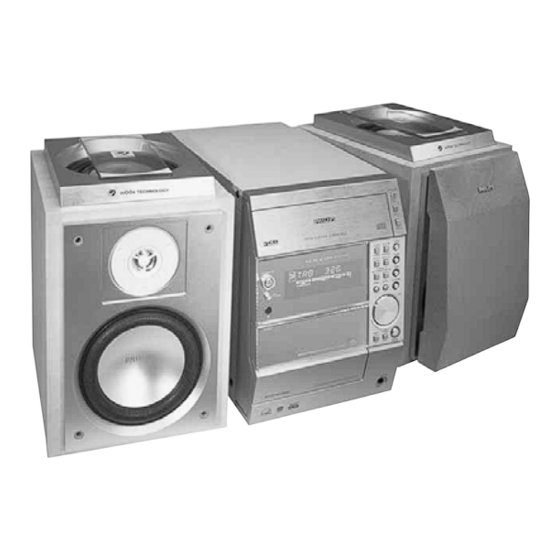
Micro System
Service
Service
Service
Service Manual
©
Copyright 2001 Philips Consumer Electronics B.V. Eindhoven, The Netherlands
All rights reserved. No part of this publication may be reproduced, stored in a retrieval system or
transmitted, in any form or by any means, electronic, mechanical, photocopying, or otherwise
without the prior permission of Philips.
Published by KC 0110 Service Audio
TABLE OF CONTENTS
Location of pc boards & Version variations ................ 1-2
Technical Specifications ............................................. 1-3
Measurement setup .................................................... 1-4
Service Aids, Safety Instruction, etc. .......................... 1-5
Instruction for use: European version excerpt .......... 2-1
Additional features .................. 2-13
Disassembly Instructions & Service positions ........... 3-1
Service Test Programs ............................................... 3-4
Set Block diagram ......................................................... 4
Set Wiring diagram ........................................................ 5
Front Display Board ....................................................... 6
ECO6 Tuner Board: System Non-Cenelec ................ 7A
System Cenelec ........................ 7B
Front Control Board ....................................................... 8
ETF6-LE Tape Module ................................................... 9
3TDC Module ............................................................... 10
Power 2001 Module ..................................................... 11
Set Mechanical Exploded view & parts list ................. 12
Printed in The Netherlands
Subject to modification
MC-70/
Page
CLASS 1
GB
21/21M/22/37
COMPACT
DIGITAL AUDIO
3139 785 22720
Advertisement
Table of Contents

Related Manuals for Philips MC-21M


Summarization of Contents
LOCATION OF PC BOARDS
VERSION VARIATIONS
Details features and board variations across different model versions.
SPECIFICATIONS
GENERAL
General system specifications including mains voltage, frequency, power consumption, and dimensions.
TUNER
FM, MW, and LW tuner specifications like tuning range, IF frequency, and sensitivity.
AMPLIFIER
Amplifier specifications covering output power, frequency response, and controls.
CASSETTE RECORDER
Cassette recorder specifications for track number, tape speed, and bias system.
COMPACT DISC
Compact disc player specifications for frequency response, signal-to-noise ratio, and channel separation.
MW
Medium Wave tuner specifications.
LW
Long Wave tuner specifications.
MEASUREMENT SETUP
Tuner FM
Setup for FM tuner measurements, including equipment and bandpass filter use.
Tuner AM (MW,LW)
Setup for AM tuner measurements in a Faraday cage.
CD
Measurement setup for CD playback using test discs and equipment.
Recorder
Measurement setup for recorder functions using test cassettes.
SERVICE AIDS
Service Tools
Lists various tools required for service, including Torx drivers and holders.
ESD Equipment
Lists anti-static equipment for preventing electrostatic discharge damage.
Cassette
Lists specific test cassettes for service procedures.
Compact Disc
Lists test discs for compact disc player service.
HANDLING CHIP COMPONENTS
GENERAL
General guidelines for handling chip components.
DISMOUNTING
Instructions and diagrams for dismounting chip components.
MOUNTING
Instructions and diagrams for mounting chip components.
PRECAUTIONS
Important precautions for handling chip components, especially soldering.
ESD WARNING
WARNINGS AND SAFETY REGULATIONS
Multilingual warnings about ESD and general safety regulations for repair.
LASER SAFETY WARNINGS
LASER SAFETY WARNINGS
Warnings about invisible laser radiation when the unit is open.
General Information
Environmental Information
Information regarding packaging materials and recycling.
Acknowledgement
Acknowledgement of ENERGY STAR partnership.
Supplied Accessories
List of accessories included with the system.
Safety Information
Essential safety precautions before operating the system.
Preparations
Rear Connections
Details on connecting antennas and speakers to the rear terminals.
Optional Connections
Information on connecting optional equipment not supplied.
Inserting Batteries into Remote Control
Instructions for inserting batteries into the remote control.
Antennas Connection
Instructions for connecting AM and FM antennas for optimal reception.
Power
Instructions for connecting the AC power cord and ensuring voltage compatibility.
Speakers Connection
Guidelines for connecting front speakers to the terminals, including impedance notes.
Optional Connections
Information on connecting optional equipment not supplied.
Subwoofer Out Connection
How to connect a subwoofer to the SUBWOOFER OUT terminal for low bass effects.
Digital Out Connection
Connecting the digital output for recording on digital audio equipment.
Controls
Controls on the system and remote control
Overview of controls on the main system unit and the remote control.
Basic Functions
Explains basic functions like Plug and Play, demonstration mode, and switching system states.
Plug and Play
How Plug and Play automatically stores RDS and radio stations.
Demonstration Mode
How to activate and deactivate the system's demonstration mode.
System Power States
How to switch the system on, to standby, or to eco power standby modes.
Power Saving Automatic Standby
Automatic standby function to save power after inactivity.
Display and Volume Control
Adjusting display brightness and audio volume levels.
Interactive Sound Control
Explanation of sound control features like BASS/TREBLE and WOOx.
Bass/Treble
How to adjust bass and treble sound settings.
IS (Incredible Surround)
How to activate or deactivate the Incredible Surround effect for wider soundstage.
CD Operation
Discs for Playback
Information on compatible CD disc types for playback.
Loading Disc
Step-by-step instructions for loading discs into the changer.
To select a desired disc tray
How to choose a specific disc tray for playback.
Playback Control
How to interrupt, stop, search, skip tracks, and replace discs.
Programming and Repeat/Shuffle
Creating track programs, setting repeat, and shuffle playback modes.
Radio Reception
Presetting Radio Stations
How to store and manage preset radio stations manually or automatically.
RDS Features
Explanation of RDS, receiving stations, and setting RDS time.
NEWS (only available in RDS radio station)
How to activate the NEWS function to automatically switch to news broadcasts.
Tape Operation/Recording
IMPORTANT!
Important notes regarding copyright and tape usage.
Preparation for Recording
Steps to prepare the system and tape deck for recording.
One Touch Recording
How to record a source with a single button press.
CD Synchro Recording
How to record CD tracks synchronized with the CD player.
External Sources
How to connect and play audio from external sources.
Digital Recording via Digital Out
Instructions for digital recording using the digital output.
General Information on Recording
General information about recording, including tape types and level settings.
Tape Playback
How to play back audio tapes.
To stop playback
How to stop tape playback.
To change the playback side
How to switch between the front and back sides of a tape.
To change the playback mode
How to select different tape playback modes (one side, both sides, repeat).
To rewind or fast forward during playback
How to fast forward or rewind tape during playback.
To rewind or fast forward when playback is stopped
How to fast forward or rewind tape when playback is stopped.
Clock/Timer
Clock Setting
How to set the system clock in 12-hour or 24-hour format.
Display Clock
How to switch between clock display and normal display modes.
Timer Setting
How to set the timer to automatically turn on the system at a preset time.
Sleep Timer Setting
How to set the sleep timer to automatically switch the system to standby.
Maintenance
Cleaning the Cabinet
How to clean the system's exterior cabinet.
Cleaning Discs
Methods for cleaning CDs to ensure good playback.
Cleaning the disc lens
How to clean the CD player's optical lens.
Cleaning the Heads and the Tape Paths
Procedures for cleaning tape heads, capstans, and pressure rollers.
Demagnetising the heads
Using a demagnetizing tape to maintain head quality.
Troubleshooting
CD and General Issues
Troubleshooting for CD errors and general system unresponsiveness.
RADIO RECEPTION
Troubleshooting steps for poor radio reception.
TAPE OPERATION/RECORDING
Troubleshooting steps for tape playback or recording problems.
Additional Features for other versions
CD Operation and Clock/Timer
Version-specific CD playback resume and clock/timer functions.
Radio Reception Tuning
Information on changing the tuning grid for specific regional versions.
DISMANTLING INSTRUCTIONS
Dismantling of the Cassette Cover
Step-by-step instructions for removing the cassette cover.
Dismantling of the 3DTC Module and Tuner Board
Instructions for disassembling the 3DTC module and tuner board.
Detaching the Front Panel assembly from the Bottom/Rear assembly
Procedure for separating the front panel from the main chassis.
Dismantling of the Front Panel assembly
Dismantling of Rear Panel
Instructions for removing the rear panel components.
Dismantling of the Bottom assembly
Steps for disassembling the bottom part of the unit.
SERVICE POSITIONS & REPAIR HINTS
Service pos A
Illustration and hints for service position A.
Service pos B
Illustration and hints for service position B.
Service pos C
Illustration and hints for service position C, noting flex wire interchange.
Service pos D
Illustration and hints for service position D.
SERVICE TEST PROGRAM
TUNER
Test programs for the tuner section, including frequency checks.
PLAY MODE
Information about the service PLAY MODE for CD function testing.
DISPLAY TEST
Test for the front display and LEDs.
Error code
Table listing error codes and their descriptions for CD mode failures.
FRONT DISPLAY BOARD
FTD Display pins connection
Pin assignment and connection details for the front display board.
Circuit diagram
Circuit diagram for the front display board.
Components & Chips Layout
Layout of components and chips on the front display board.
Electrical parts list
List of electrical parts used on the front display board.
COMPONENT LAYOUT
CHIP LAYOUT
Layout diagram showing the placement of integrated circuits (chips).
ELECTRICAL PARTS LIST - FRONT DISPLAY BOARD
MISCELLANEOUS
List of miscellaneous electronic parts for the front display board.
CAPACITORS
List of capacitors used on the front display board.
RESISTORS
List of resistors used on the front display board.
ELECTRICAL PARTS LIST - FRONT DISPLAY BOARD
RESISTORS
Continuation of resistor list for the front display board.
COILS & FILTERS
List of coils and filters for the front display board.
DIODES
List of diodes used on the front display board.
TRANSISTORS & INTEGRATED CIRCUITS
List of transistors and ICs for the front display board.
ECO6 Tuner Board
Blockdiagram
Block diagram illustrating the ECO6 Tuner Board system.
Schematic Diagram
Detailed schematic diagram of the ECO6 Tuner Board.
Component Layout
Layout of components on the ECO6 Tuner Board.
Adjustment table
Table listing adjustment points and values for the tuner board.
Electrical Partslist
List of electrical parts for the ECO6 Tuner Board.
TUNER BOARD ECO6 / SYSTEMS NON CENELEC
LEGEND
Explanation of symbols and notations used in the tuner board diagram.
VERSION PROGRAMMING COMPONENTS
Components related to version programming on the tuner board.
Signal path
Diagram illustrating signal flow within the tuner board.
TUNER BOARD ECO6 Systems non Cenelec/componentside view
TUNER ADJUSTMENT TABLE
Table detailing tuning adjustments for FM, MW, and LW bands.
FM
Adjustment procedures for FM reception.
MW
Adjustment procedures for Medium Wave reception.
LW
Adjustment procedures for Long Wave reception.
FM - IF
IF adjustment for FM reception.
FM - VCO
VCO adjustment for FM reception.
AM IF
IF adjustment for AM reception.
Electrical Partslist ECO6 SYSTEMS NON-CENELEC
MISCELLANEOUS
List of miscellaneous parts for the ECO6 tuner board.
CAPACITORS
List of capacitors for the ECO6 tuner board.
RESISTORS
List of resistors for the ECO6 tuner board.
COILS
List of coils for the ECO6 tuner board.
DIODES
List of diodes for the ECO6 tuner board.
TRANSISTORS
List of transistors for the ECO6 tuner board.
ECO6 Tuner Board
Blockdiagram
Block diagram of the ECO6 Tuner Board (Systems Cenelec version).
Schematic Diagram
Schematic diagram for the ECO6 Tuner Board (Systems Cenelec version).
Component Layout
Layout of components on the ECO6 Tuner Board (Systems Cenelec version).
Adjustment table
Adjustment table for the ECO6 Tuner Board (Systems Cenelec version).
Electrical Partslist
Electrical parts list for the ECO6 Tuner Board (Systems Cenelec version).
TUNER BOARD ECO6 / SYSTEMS CENELEC
LEGEND
Explanation of symbols used in the tuner board schematic.
VERSION PROGRAMMING COMPONENTS
Components related to version programming.
Signal path
Diagram illustrating signal flow for the tuner board.
TUNER BOARD ECO6 Systems - Cenelec/componentside view
TUNER ADJUSTMENT TABLE
Tuning adjustment table for ECO6 Cenelec versions.
FM
FM tuning adjustment procedures.
MW
MW tuning adjustment procedures.
LW
LW tuning adjustment procedures.
FM - IF
FM Intermediate Frequency adjustment.
FM - VCO
FM Voltage Controlled Oscillator adjustment.
AM IF
AM Intermediate Frequency adjustment.
FRONT CONTROL BOARD
Standby (Power) part
Circuit and layout details for the standby and power section.
Key Control (KEYB. 1) & Lightwash parts
Circuit and layout for key control and lightwash functions.
Headphone, Jog (Volume) and CDC Key parts
Circuit and layout for headphone, jog dial, and CDC key controls.
Electrical parts list
List of electrical parts for the front control board.
KEY CONTROL (KEYB. 1) PART - CIRCUIT & LAYOUT DIAGRAMS
LIGHTWASH PART - CIRCUIT & LAYOUT DIAGRAMS
Circuit and layout diagrams for the lightwash function.
HEADPHONE PART - CIRCUIT & LAYOUT DIAGRAMS
JOG (VOLUME) PART - CIRCUIT & LAYOUT DIAGRAMS
Circuit and layout for the jog dial and volume control.
CDC KEY PART-CIRCUIT & LAYOUT DIAGRAMS
Circuit and layout for the CDC (Compact Disc Control) keys.
ETF6-LE TAPE MODULE
Block Diagram
Block diagram of the ETF6-LE Tape Module.
Brief Introduction & Connector assignment
Overview of the tape module and its connector assignments.
Tape Module Wiring & variation table
Wiring details and variation table for the tape module.
Tape Mechanism electronics & Tape adjustments
Details on tape mechanism electronics and adjustment procedures.
ETF board layouts - Components & Chips
Layout of components and chips on the ETF board.
Analog Circuit diagram
Analog circuit diagram for the tape module.
Exploded views & parts list
Exploded view and parts list for the tape module.
Brief Introduction to Tape Module
Playback and Recording Signal Paths
Explanation of signal processing for playback, recording, and mode selection.
Tape Module IC Functions
Detailed functions of IC7740, IC7730, ALC, and muting circuits.
Connector Assignments and Abbreviations
Lists connectors and document abbreviations.
TAPE ADJUSTMENT & CHECK TABLE
Variation table for Analog Circuit
Table showing variations in analog circuit parameters for different tape types.
MOTOR SPEED
Table for checking and adjusting motor speed.
WOW & FLUTTER
Table for checking and adjusting tape wow and flutter.
PLAYBACK LEVEL & FREQ. RESPONSE
Table for checking playback level and frequency response.
ADJUST AZIMUTH
Table for adjusting tape head azimuth.
ADJUST BIAS CURRENT
Table for adjusting bias current.
CHECK RECORD/PLAYBACK FREQUENCY AND DISTORTION
Procedures for checking recording and playback performance.
TAPE MECHANISM ELECTRONICS
Diagram and explanation of tape mechanism electronics.
COMPONENT LAYOUT
CHIP LAYOUT
Layout diagram showing chip component placement on the ETF6-LE tape module.
SERVO CONTROL CIRCUIT
SERVO CONTROL CCTRY
Circuit diagram for the servo control system.
Items used for pcb testing only
Notes on items for PCB testing only.
3DTC Module
Servicing hints
Hints and tips for servicing the 3DTC module.
Wiring
Wiring diagrams for the 3DTC module.
Brief description
A brief overview of the 3DTC module's functionality.
Blockdiagram
Block diagram of the 3DTC module.
Component Layout Main Board
Component layout for the main board of the 3DTC module.
Circuit Diagram part1
First part of the circuit diagram for the 3DTC module.
Exploded View
Exploded view of the 3DTC module for mechanical parts identification.
Mechanical Partslist
List of mechanical parts for the 3DTC module.
Electrical Partslist
List of electrical parts for the 3DTC module.
Brief description
Initial State and Tray Open
Describes the initial power-on state and the tray-open position of the changer.
3. Carriage extra.
Explains the carriage-extra position for access and disc change.
Location of switches
Identifies the locations of the seven switches used for changer functions.
Truth Table
Function
Table detailing functions based on register outputs or switch states.
Timing Diagrams
1. Open #3
Timing diagram for the open #3 action.
2. Close #3
Timing diagram for the close #3 action.
3. Select #2
Timing diagram for selecting carriage #2.
4. Select #1
Timing diagram for selecting carriage #1.
Load all discs
Loading Discs Sequence
Step-by-step guide with diagrams for loading all discs into the changer.
Change 'backwards'
E.g. select #3 while playing #1.
Example of changing discs backwards, selecting carriage #3 while playing #1.
Change 'forwards'
E.g. select #2 while playing #1.
Example of changing discs forwards, selecting carriage #2 while playing #1.
BLOCK DIAGRAM 3DTC
CD MECHANISM
Diagram of the CD mechanism unit.
MAINBOARD
Block diagram of the main board.
SIGNAL PROCESSOR CD10
Block diagram of the signal processor IC.
SHIFT REGISTER
Block diagram of the shift register.
Motor Driver
Block diagram of the motor driver circuit.
SERVO CONTROL
Block diagram of the servo control system.
MicroProcessor Control / Communication lines
Lines for microprocessor control and communication.
Mainboard Componentside view
Mainboard Copperside view
Layout of components on the copperside of the mainboard.
3DTC-mainboard part 1
HF-Amplifier & Laser power control
Circuit details for HF amplifier and laser power control.
Servo Driver
Circuit details for the servo driver.
Motor Driver
Circuit details for the motor driver.
EYE-PATTERN
Diagram illustrating the eye pattern measurement.
DC voltages measured in PLAY MODE
Table of DC voltages measured in play mode.
3DTC-mainboard part 2
PHOTO DIODES
Circuit details related to photodiodes.
Signal Processor SAA7324/SAA7325
Circuit details for the signal processor IC.
Laser Control
Circuit details for laser diode control.
Active Low-Pass Filter
Circuit details for the active low-pass filter.
DC voltages measured in PLAY MODE
Table of DC voltages measured in play mode.
3DTC-mainboard part 3
Changer Control Logic
Circuit details for the changer control logic.
Motor Driver
Circuit details for the motor driver.
3Disc Tray Changer
Exploded view
Exploded view of the 3Disc Tray Changer mechanism.
MECHANICAL PARTS
List of mechanical parts for the 3Disc Tray Changer.
POWER 2001 Module
Brief Circuit Description
Description of the circuit details, focusing on the amplifier.
Block Diagram
Block diagram of the POWER 2001 Module.
Mains Board
Details about the Mains Board.
Combi Board
Details about the Combi Board.
Regulator Board
Details about the Regulator Board.
Circuit details continued
Low power standby feature
Explanation of the low power standby functionality.
DC voltages +A1, +B1, +C1
Description of DC voltages supplied to the Super Class G amplifier.
Generation of +A1
How the +A1 DC voltage is generated.
Generation of +B1
How the +B1 DC voltage is generated.
Generation of +C1
How the +C1 DC voltage is generated.
Blockdiagram Power 2001 40W Super-G
MAINS BOARD
Block diagram of the Mains Board.
COMBI BOARD
Block diagram of the Combi Board, including source selector and amplifier stages.
REGULATOR BOARD
Block diagram of the Regulator Board.
MAINS Board
DC voltages measured with low output power
Table of DC voltages measured during low output power conditions.
DC voltages measured in PLAY MODE
Table of DC voltages measured during play mode.
COMBI BOARD
Copperside view
Copperside component layout of the Combi Board.
COMBI BOARD AMPLIFIER PART
BUFFER AMPLIFIER
Circuit details for the buffer amplifier stages.
POWER STAGE
Circuit details for the power amplifier stages.
SUPER-G SWITCHES
Circuit details for the Super Class G switching components.
Source Selector part
Circuit details for the source selector.
Circuit Diagram Regulator Board
Version Specific Notes
Notes regarding components or circuits specific to certain versions.
ELECTRICAL PARTSLIST POWER2001 40W Super-G Regulator Board
MISCELLANEOUS
List of miscellaneous parts for the regulator board.
CAPACITORS
List of capacitors for the regulator board.
RESISTORS
List of resistors for the regulator board.
DIODES
List of diodes for the regulator board.
TRANSISTORS
List of transistors for the regulator board.
INTEGRATED CIRCUITS
List of integrated circuits for the regulator board.
EXPLODED VIEW - MAIN UNIT
LEGEND
Explanation of symbols used in the exploded view.
DETAILS VARY DEPENDING ON MODELS/VERSIONS
Note that details may differ based on model or version.
MODELS WITH WOOX FEATURE ONLY
Indication of parts specific to models with WOOx feature.
MODELS WITH LOW POWER STANDBY FEATURE ONLY
Indication of parts specific to models with low power standby feature.
MECHANICAL & ACCESSORIES PARTS LIST - MAIN UNIT
SCREW LISTS - MAIN UNIT
List of screws used in the main unit.
SCREW LISTS - Power 2001 Module
List of screws specific to the Power 2001 Module.
Need help?
Do you have a question about the MC-21M and is the answer not in the manual?
Questions and answers