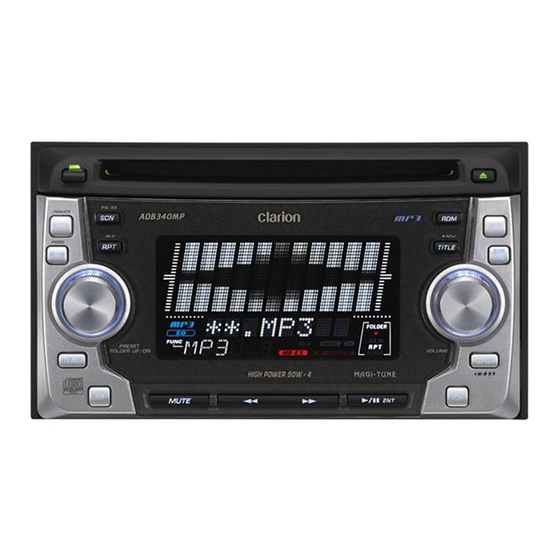
Clarion ADB341MP Service Manual
2din am/fm
cd/mp3 cassette player
Hide thumbs
Also See for ADB341MP:
- Owner's manual (18 pages) ,
- Owner's manual (18 pages) ,
- Owner's manual (26 pages)
Advertisement
Table of Contents
- 1 Electrical Parts List
- 2 Specifications
- 3 Troubleshooting
- 4 In Case of Difficulty
- 5 Error Displays
- 6 Block Diagram
- 7 Exploded View Parts List
- 8 Static Electricity
- 9 Electrical Parts List
- 10 Circuit Diagram
- 11 Printed Wiring Board
- 12 Component Side
- 13 Solder Side
- Download this manual
See also:
Owner's Manual
ADB340MP
REISSUE NOTIFICATION /
REPLACEMENT REQUEST
ORIGINAL SERVICE MANUAL
This additional service manual is designed to be used to-
gether with the original manual.
Original model
ADB340MP(PE-2652B)
ADB341MP(PE-2653K)
EXPODED VIEW / PARTS LIST
Main section (cf.page 10)
* The following part was modified.
It is possible to use a new CD mechanism(P/No. 653-
0435-12) for an old unit. It is impossible to use a old CD
mechanism(P/No. 653-0428-10) for a new unit.
[Serial No.] ADB340MP : from 4817
ADB341MP : from 9864
NO. PART NO.
DESCRIPTION
11
653-0435-12 CD MECH(CDC03TL2)
CD mechanism section (cf.page 12-13)
* The following parts were modified.
[Serial No.] ADB340MP : from 4817
ADB341MP : from 9864
NO. PART NO.
DESCRIPTION
1
653-0435-18 CHASSIS
5
653-0435-19 TOP COVER
11
653-0435-20 DISC ARM L
12
653-0435-21 DISC ARM R
13
653-0435-22 TOP GUIDE
43
653-0435-23 CHACK SHEET
64
653-0435-24 MACHINE SCREW
Clarion Co., Ltd.
50 Kamitoda, Toda-shi, Saitama 335-8511 Japan
Service Dept.: 5-66 Azuma , Kitamoto-shi, Saitama 364-0007 Japan
Tel: +81-48-541-2335 / 2432 FAX: +81-48-541-2703
Manual No.
298-6153-00
Q'TY
1
Q'TY
1
1
1
1
1
1
5
- 1 -
Service Manual
2DIN AM/FM
CD/MP3 Cassette Player
Model
(PE-2652B / For U.S.A.)
Model
(PE-2653K / For other countries)
ELECTRICAL PARTS LIST
Display PWB(B3) section (cf.page 17)
* The following part was modified.
[Serial No.] ADB340MP : from 5971
ADB341MP : from 14930
REF No. PART No.
D902
653-0435-17 DI-HZM5.1-B1
Published by Service Dept.
298-6153-01
Mar.2006
Printed in Japan
DESCRIPTION
ADB340MP
ADB341MP
Advertisement
Table of Contents

Related Manuals for Clarion ADB341MP


Summarization of Contents
Service Manual Revisions
Original Service Manual Updates
This additional service manual is designed to be used together with the original manual.
Parts Lists and Diagrams
Exploded View - Main Section
Main section exploded view and parts list.
Exploded View - CD Mechanism Section
CD mechanism section exploded view and parts list.
Electrical Parts List - Display PWB
Electrical parts list for the display PWB section.
Specifications
Tuner Section Specifications (FM/AM)
Specifications for the FM and AM tuner sections.
Playback Section Specifications (CD/MP3/Tape)
Specifications for CD player, MP3 mode, and tape deck sections.
Audio and General Specifications
Audio section output and general unit specifications.
Important Notes
General notes and precautions for the unit's operation.
Component Details and Safety
Component List (Models PE-2652B-A / PE-2653K-A)
List of components for models PE-2652B-A and PE-2653K-A.
General Repair Cautions
General safety cautions and precautions for repair work.
Guidance for Repair Engineers
Specific instructions and safety guidance for engineers performing repairs.
Troubleshooting Common Issues
General Difficulty Troubleshooting
Troubleshooting steps for general operational difficulties.
CD/MP3 Disc Errors
Common errors related to CD and MP3 disc playback.
Tape Playback Issues
Troubleshooting steps for common tape playback problems.
Integrated Circuit (IC) Pin Explanations
Microcomputer IC (uPD178078GF-667-3)
Pin explanation for the main microcomputer IC.
Quad Bridge Power Amplifier IC (TA8275H)
Pin explanation for the quad bridge power amplifier IC.
Sub Microcomputer IC (M30621M8A8E7GP)
Pin explanation for the sub microcomputer IC.
Electric Volume/Tone Controller IC (LC75410WS)
Pin explanation for the electric volume and tone controller IC.
Septet Band Pass Filter IC (BA3834F)
Pin explanation for the band pass filter IC.
Digital Signal Processor IC (TC94A20F)
Pin explanation for the digital signal processor IC.
Head Amplifier IC (TA2157FN)
Pin explanation for the head amplifier IC.
Digital Signal Processor IC (TC94A14FA)
Pin explanation for another digital signal processor IC.
Bidirectional Motor Driver IC (LB1641)
Pin explanation for the bidirectional motor driver IC.
Tape Pre-amplifier IC (BA3430FS)
Pin explanation for the tape pre-amplifier IC.
Dual Operational Amplifier IC (LA6458M)
Pin explanation for the dual operational amplifier IC.
Exploded Views and Parts List
Main Section Parts List
Detailed parts list for the main section of the unit.
Electrical Parts List
Main PWB(B1) Section Components
List of electrical components for the Main PWB(B1) section.
Sub PWB(B2) Section Components
List of electrical components for the Sub PWB(B2) section.
Display PWB(B3) Section Components
List of electrical components for the Display PWB(B3) section.
Servo PWB(B4) Section Components
List of electrical components for the Servo PWB(B4) section.
Switch-A PWB(B5) Section Components
List of electrical components for the Switch-A PWB(B5) section.
Switch-B PWB(B6) Section Components
List of electrical components for the Switch-B PWB(B6) section.
Reel PWB(B7) Section Components
List of electrical components for the Reel PWB(B7) section.
Circuit Diagrams
Main PWB(B1) Section Circuit Diagram (1/3)
First part of the circuit diagram for the Main PWB(B1).
Reel PWB(B7) Section Circuit Diagram
Circuit diagram for the Reel PWB(B7) section.
Main PWB(B1) Section Circuit Diagram (2/3)
Second part of the circuit diagram for the Main PWB(B1).
Sub PWB(B2) Section Circuit Diagram
Circuit diagram for the Sub PWB(B2) section.
Main PWB(B1) Section Circuit Diagram (3/3)
Third part of the circuit diagram for the Main PWB(B1).
Printed Wiring Board Layouts
Main PWB(B1) Layout (1/2)
First part of the printed wiring board layout for Main PWB(B1).
Sub PWB(B2) Layout (1/2)
First part of the printed wiring board layout for Sub PWB(B2).
Main PWB(B1) Layout (2/2)
Second part of the printed wiring board layout for Main PWB(B1).
Sub PWB(B2) Layout (2/2)
Second part of the printed wiring board layout for Sub PWB(B2).
Reel PWB(B7) Section Layout
Printed wiring board layout for the Reel PWB(B7) section.
Display PWB(B3) Section Layout
Printed wiring board layout for the Display PWB(B3) section.
Circuit Diagrams (Continued)
Servo PWB(B4) Section Circuit Diagram
Circuit diagram for the Servo PWB(B4) section.
Switch-A PWB(B5) Section Circuit Diagram
Circuit diagram for the Switch-A PWB(B5) section.
Switch-B PWB(B6) Section Circuit Diagram
Circuit diagram for the Switch-B PWB(B6) section.
Servo PWB(B4) Section Layout (2/2)
Second part of the printed wiring board layout for Servo PWB(B4).
Need help?
Do you have a question about the ADB341MP and is the answer not in the manual?
Questions and answers