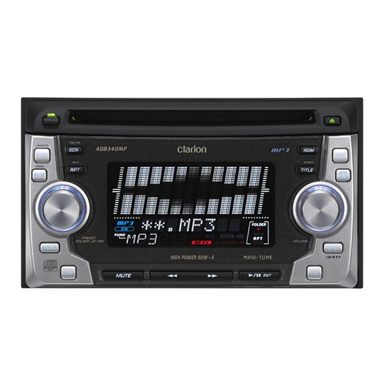
Clarion ADB340MP Service Manual
2din am/fm
cd/mp3 cassette player
Hide thumbs
Also See for ADB340MP:
- Owner's manual (26 pages) ,
- Installation/wire connection manual (2 pages) ,
- Owner's manual (18 pages)
Advertisement
Table of Contents
- 1 Electrical Parts List
- 2 Specifications
- 3 Troubleshooting
- 4 In Case of Difficulty
- 5 Error Displays
- 6 Block Diagram
- 7 Exploded View Parts List
- 8 Static Electricity
- 9 Electrical Parts List
- 10 Circuit Diagram
- 11 Printed Wiring Board
- 12 Component Side
- 13 Solder Side
- Download this manual
See also:
Owner's Manual
ADB340MP
REISSUE NOTIFICATION /
REPLACEMENT REQUEST
ORIGINAL SERVICE MANUAL
This additional service manual is designed to be used to-
gether with the original manual.
Original model
ADB340MP(PE-2652B)
ADB341MP(PE-2653K)
EXPODED VIEW / PARTS LIST
Main section (cf.page 10)
* The following part was modified.
It is possible to use a new CD mechanism(P/No. 653-
0435-12) for an old unit. It is impossible to use a old CD
mechanism(P/No. 653-0428-10) for a new unit.
[Serial No.] ADB340MP : from 4817
ADB341MP : from 9864
NO. PART NO.
DESCRIPTION
11
653-0435-12 CD MECH(CDC03TL2)
CD mechanism section (cf.page 12-13)
* The following parts were modified.
[Serial No.] ADB340MP : from 4817
ADB341MP : from 9864
NO. PART NO.
DESCRIPTION
1
653-0435-18 CHASSIS
5
653-0435-19 TOP COVER
11
653-0435-20 DISC ARM L
12
653-0435-21 DISC ARM R
13
653-0435-22 TOP GUIDE
43
653-0435-23 CHACK SHEET
64
653-0435-24 MACHINE SCREW
Clarion Co., Ltd.
50 Kamitoda, Toda-shi, Saitama 335-8511 Japan
Service Dept.: 5-66 Azuma , Kitamoto-shi, Saitama 364-0007 Japan
Tel: +81-48-541-2335 / 2432 FAX: +81-48-541-2703
Manual No.
298-6153-00
Q'TY
1
Q'TY
1
1
1
1
1
1
5
- 1 -
Service Manual
2DIN AM/FM
CD/MP3 Cassette Player
Model
(PE-2652B / For U.S.A.)
Model
(PE-2653K / For other countries)
ELECTRICAL PARTS LIST
Display PWB(B3) section (cf.page 17)
* The following part was modified.
[Serial No.] ADB340MP : from 5971
ADB341MP : from 14930
REF No. PART No.
D902
653-0435-17 DI-HZM5.1-B1
Published by Service Dept.
298-6153-01
Mar.2006
Printed in Japan
DESCRIPTION
ADB340MP
ADB341MP
Advertisement
Table of Contents


Need help?
Do you have a question about the ADB340MP and is the answer not in the manual?
Questions and answers