Table of Contents
Advertisement
QQ
3 7 63 1515 0
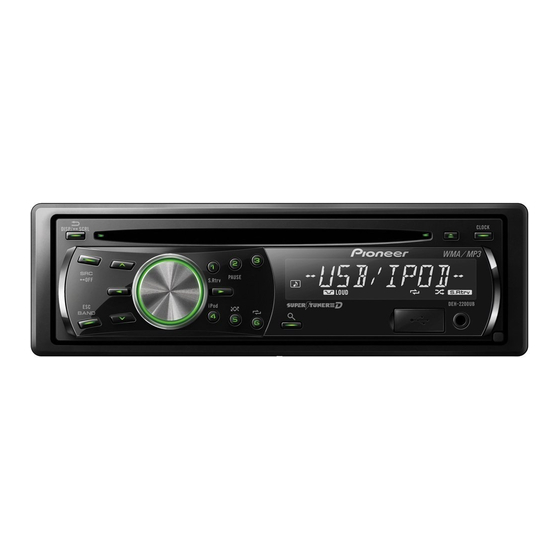
CD RDS RECEIVER
DEH-2200UB
DEH-2200UBB
DEH-2220UB
DEH-2210UB
TE
L 13942296513
This service manual should be used together with the following manual(s):
Model No.
CX-3269
CRT4488
www
For details, refer to "Important Check Points for Good Servicing".
.
PIONEER CORPORATION
PIONEER ELECTRONICS (USA) INC. P.O. Box 1760, Long Beach, CA 90801-1760, U.S.A.
PIONEER EUROPE NV Haven 1087, Keetberglaan 1, 9120 Melsele, Belgium
PIONEER ELECTRONICS ASIACENTRE PTE. LTD. 253 Alexandra Road, #04-01, Singapore 159936
PIONEER CORPORATION 2009
http://www.xiaoyu163.com
Order No.
Mech. Module
S11iPod/USB
x
ao
y
i
4-1, Meguro 1-chome, Meguro-ku, Tokyo 153-8654, Japan
http://www.xiaoyu163.com
8
DEH-2200UB/XSEW5
/XSEW5
/XSEW5
/XSUR
Q Q
3
6 7
1 3
CD Mech. Module : Circuit Descriptions, Mech. Descriptions, Disassembly
u163
.
2 9
9 4
2 8
1 5
0 5
8
2 9
9 4
Remarks
m
co
K-ZZZ. SEPT. 2009 Printed in Japan
9 9
ORDER NO.
CRT4455
/XSEW5
2 8
9 9
Advertisement
Table of Contents

Related Manuals for Pioneer DEH-2220UB XSEW5


Summarization of Contents
Safety Information
General Safety Precautions
Safety guidelines for service technicians, including laser safety.
Service Precautions and Notes
Service Precautions
Detailed safety guidelines and handling of ICs.
Notes on Soldering
Guidance on using lead-free solder and proper soldering techniques.
Installation Checks
Procedure to check for mech. assembly installation and error indications.
Specifications
General and Audio Specifications
Unit dimensions, weight, power output, load impedance, and tone controls.
Tuner and CD Player Specs
FM, MW, LW tuner details and CD player performance metrics.
USB and Disc Format
USB standard specs and supported disc/content formats.
Basic Service Items
Post-Servicing Check Points
Procedures to confirm proper operation and resolve customer complaints.
Block Diagrams
Tuner Amp Unit Block Diagram
Functional block diagram of the tuner amplifier section.
CD Core Unit Block Diagram
Block diagram for the CD mechanism, CPU, and USB host.
Diagnosis
Operational Flowchart
Step-by-step process for diagnosing unit startup and operation.
Service Mode
Display Test Mode Operations
Procedures to enter and operate the display test modes.
Disassembly Procedures
Removing External Components
Steps for removing the case, panel assembly, and tuner amp unit.
Removing CD Mechanism Module
Procedures for disconnecting and removing the CD mechanism module.
Settings and Adjustments
CD Adjustment Procedures
Cautions and steps for adjusting the CD mechanism module.
Exploded Views and Parts Lists
Packing Exploded View and Parts
Diagram and list of components for product packaging.
Schematic Diagrams
Tuner Amp Unit Schematic
Circuit diagram for the tuner amplifier section, detailing components and connections.
PCB Connection Diagrams
Tuner Amp Unit PCB Connections
Diagram showing component placement and connections on the tuner amp PCB.
Electrical Parts List
Integrated Circuits and Transistors
List of ICs and transistors with part numbers and locations.
Diodes, Varistors, and Inductors
List of diodes, varistors, and inductors with part numbers and locations.
Resistors and Capacitors
Lists of resistors and capacitors with part numbers and locations.
Need help?
Do you have a question about the DEH-2220UB XSEW5 and is the answer not in the manual?
Questions and answers