Table of Contents
Advertisement
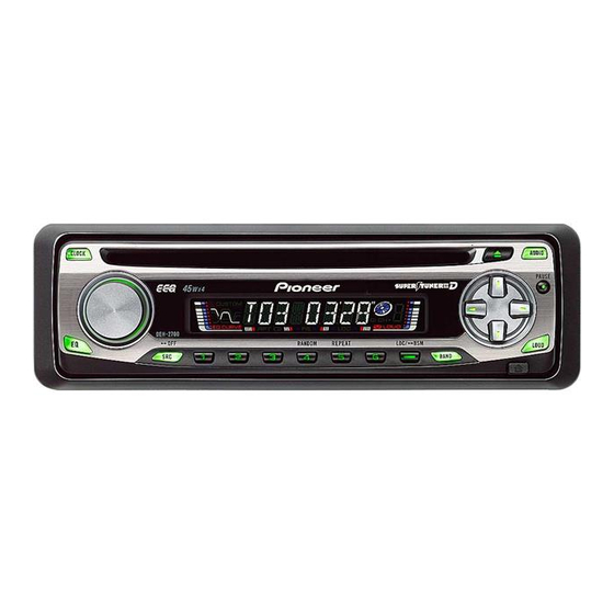
HIGH POWER CD PLAYER WITH FM/AM TUNER
DEH-2700
This service manual should be used together with the following manual(s):
Model No.
Order No.
CX-3110
CRT3178
For details, refer to "Important Check Points for Good Servicing".
PIONEER CORPORATION
PIONEER ELECTRONICS (USA) INC. P.O. Box 1760, Long Beach, CA 90801-1760, U.S.A.
PIONEER EUROPE NV Haven 1087, Keetberglaan 1, 9120 Melsele, Belgium
PIONEER ELECTRONICS ASIACENTRE PTE. LTD. 253 Alexandra Road, #04-01, Singapore 159936
PIONEER CORPORATION 2004
Mech.Module
S10.1
CD Mech. Module : Circuit Description, Mech. Description, Disassembly
4-1, Meguro 1-chome, Meguro-ku, Tokyo 153-8654, Japan
DEH-2700/XU/UC
/XU/UC
Remarks
ORDER NO.
CRT3363
K-ZZA. NOV. 2004 Printed in Japan
Advertisement
Table of Contents

Related Manuals for Pioneer DEH-2700/XU/UC


Summary of Contents for Pioneer DEH-2700/XU/UC
- Page 1 PIONEER CORPORATION 4-1, Meguro 1-chome, Meguro-ku, Tokyo 153-8654, Japan PIONEER ELECTRONICS (USA) INC. P.O. Box 1760, Long Beach, CA 90801-1760, U.S.A. PIONEER EUROPE NV Haven 1087, Keetberglaan 1, 9120 Melsele, Belgium PIONEER ELECTRONICS ASIACENTRE PTE. LTD. 253 Alexandra Road, #04-01, Singapore 159936 PIONEER CORPORATION 2004 K-ZZA.
-
Page 2: Safety Information
ICs inside the unit. 3. To protect the pickup unit from electrostatic discharge during servicing, take an appropriate treatment (shorting-solder) by referring to "the DISASSEMBLY". 4. After replacing the pickup unit, be sure to check the grating. DEH-2700/XU/UC... - Page 3 To protect products from damages or failures during transit, the shipping mode should be set or the shipping screws should be installed before shipment. Please be sure to follow this method especially if it is specified in this manual. DEH-2700/XU/UC...
-
Page 4: Table Of Contents
7. GENERAL INFORMATION ..........................44 7.1 DIAGNOSIS ............................. 44 7.1.1 DISASSEMBLY ............................. 44 7.1.2 CONNECTOR FUNCTION DESCRIPTION ..................47 7.2 PARTS..............................48 7.2.1 IC ................................48 7.2.2 DISPLAY ............................... 52 7.3 OPERATIONAL FLOW CHART ....................... 53 7.4 CLEANING............................... 54 8. OPERATIONS ..............................55 DEH-2700/XU/UC... -
Page 5: Specifications
1. SPECIFICATIONS DEH-2700/XU/UC... -
Page 6: Exploded Views And Parts List
• Screw adjacent to mark on the product are used for disassembly. • For the applying amount of lobricants or glue, follow the instructions in this manual. (In the case of no amount instructions,apply as you think it appropriate.) 2.1 PACKING DEH-2700/XU/UC... - Page 7 16-3 Caution Card CRP1294 Screw TRZ50P080FTC 16-4 Caution Card CRP1310 Polyethylene Bag CEG-158 16-5 Card ARY1048 Handle CNC5395 Bush CNV3930 Cord Assy XDE7008 Polyethylene Bag CEG1173 Owner's Manual,Installation Manual Part No. Language YRD5013 English, French, Spanish YRD5017 English, French, Spanish DEH-2700/XU/UC...
-
Page 8: Exterior
2.2 EXTERIOR DEH-2700/XU/UC... - Page 9 YAA5001 Button(DETACH) YAC5027 Button(SOURCE) YAC5030 Button(1-6, LOCAL/BSM) YAC5031 Button(AUDIO, LOUDNESS) YAC5032 Button(BAND) YAC5033 Button(EJECT, PAUSE) YAC5034 Button(DOWN, RIGHT) YAC5035 Button(UP, LEFT) YAC5036 Button(CLOCK, EQ) YAC5039 Spring YBL5001 Cover YNS5038 Connector(CN1801) CKS4943 Sheet CNM7932 Connector CNV7369 LCD(LCD1801) YAW5021 Holder YNC5005 DEH-2700/XU/UC...
-
Page 10: Cd Mechanism Module
2.3 CD MECHANISM MODULE 1GEM1024 2GEM1045 3GEM1035 DEH-2700/XU/UC... - Page 11 CND2712 Bracket CND1895 Screw JFZ20P020FTC CNC9968 Screw JGZ17P022FTC CND1909 ••••• Lever CND2032 Washer YE20FTC Pickup Unit(P10)(Service) CXX1647 Lever CNC9984 Sheet CNM8134 Screw IMS26P030FTC Collar CNV8447 Spring CBL1635 Guide CNV8448 Clamper CNV8372 CNV8403 Rack CNV8374 Holder CNV8376 Holder CNV8377 CNV8378 DEH-2700/XU/UC...
-
Page 12: Block Diagram And Schematic Diagram
IC 201 DRIVER MOTOR HOME UPD63712AGC LCOM LOADING/ CARRIAGE LOEJ CDLOEJ MOTOR LCOP LOEJ LOEJ/NC CONT CONT CONT CONT/NC IC 301 BA5835FP DSCSNS DSCSNS DSCSENS Q991 B.UP Q992 12EJ DSCSNS 3.3V REGULATOR 3R3V IC 701 VDCONT/BRSQ VDSENS NJM2391DL1-33 VDSENS DEH-2700/XU/UC... - Page 13 SOURCE DSENS DSENSE DSENSE Q821 B.UP VDCONT/BRSQ Q822 KEY MATRIX VDSENS ILMPW LAMP IL1801 S1827 ROT1 SWVDD ROT1 ROT0 ROT0 KEY DATA VOLUME X1801 5MHz DPDT DPDT DPDT LCD DRIVER/ KEY CONTROLLER KYDT KYDT KYDT IC 1801 LCD1801 PD6340A DEH-2700/XU/UC...
-
Page 14: Overall Connection Diagram(Guide Page)
Code Practical value 12k ohms 0.01uF 10k ohms 101/10 100uF/10V The > mark found on some component parts indicates the importance of the safety factor of the part. Therefore, when replacing, be sure to use parts of identical designation. DEH-2700/XU/UC... - Page 15 TUNER AMP UNIT REAR L CH > REAR R CH +3.6dBs -6.9dBs E.VOL. CD:+10.45dBs FM: +29.6dBs AM: +19.1dBs CD:+36.45dBs CEK1208 > 600µH WIRED REMOTE CONTROL DEH-2700/XU/UC...
- Page 16 DEH-2700/XU/UC...
- Page 17 DEH-2700/XU/UC...
- Page 18 DEH-2700/XU/UC...
- Page 19 DEH-2700/XU/UC...
-
Page 20: Keyboard Unit
3.3 KEYBOARD UNIT 5MHz YAW5021 DEH-2700/XU/UC... - Page 21 KEYBOARD UNIT 40mA,14V DEH-2700/XU/UC...
-
Page 22: Cd Mechanism Module
3.4 CD MECHANISM MODULE PICKUP UNIT(P10)(SERVICE) MOTOR DRIVER CXC4440 SPINDLE MOTOR CXB8933 LOADING/CARRIAGE MOTOR 3.3V REGULATOR DEH-2700/XU/UC... - Page 23 S904:12EJ SWITCH.....ON-OFF S905:8EJ SWITCH....ON-OFF The underlined indicates the switch position. SIGNAL LINE RF AMP / SERVO / DSP DAC / LPF FOCUS SERVO LINE TRACKING SERVO LINE CARRIAGE SERVO LINE SPINDLE SERVO LINE CD CORE UNIT(S10) CN721 7.5V 7.5V DEH-2700/XU/UC...
- Page 24 # RFAGC 500mV/div 200ms/div 500mV/div 2ms/div 1V/div 500µs/div ! FE # RFAGC 0 TE 500mV/div 500mV/div 500mV/div 7 TIN 500mV/div Focus Search When "Tracking Open" 1 Track Jump Ref.: Ref.: Ref.: REFO REFO REFO Mode: Mode: Mode: TEST TEST TEST DEH-2700/XU/UC...
- Page 25 1V/div 200µs/div 5V/div 200ms/div 5V/div 200ms/div % ROUT 2 CLCONT 2 CLCONT 1V/div 5V/div 5V/div 3 LOEJ 3 LOEJ 5V/div 5V/div Analog Audio When "Eject"(12cm CD) When "Eject"(8cm CD) Ref.: Ref.: Ref.: AGND Mode: Mode: Mode: Normal Normal Normal DEH-2700/XU/UC...
-
Page 26: Pcb Connection Diagram
For further information for respective destinations, be sure WIRED REMOTE CONTROL to check with the schematic dia- CORD ASSY gram. 2.Viewpoint of PCB diagrams Capacitor Connector SIDE A SIDE B P.C.Board Chip Part CN701 DEH-2700/XU/UC... - Page 27 SIDE A ANTENNA CN1801 FRONT DEH-2700/XU/UC...
- Page 28 TUNER AMP UNIT TEST DEH-2700/XU/UC...
- Page 29 SIDE B DEH-2700/XU/UC...
-
Page 30: Keyboard Unit
4.2 KEYBOARD UNIT KEYBOARD UNIT SIDE A LCD1801 DEH-2700/XU/UC... - Page 31 KEYBOARD UNIT SIDE B CN831 DEH-2700/XU/UC...
-
Page 32: Cd Core Unit(S10)
4.3 CD CORE UNIT(S10) CD CORE UNIT(S10) SIDE A LOADING /CARRIAGE MOTOR SPINDLE MOTOR CN721 HOME REFO1 DEH-2700/XU/UC... - Page 33 CD CORE UNIT(S10) SIDE B 12EJ DSCSNS DEH-2700/XU/UC...
-
Page 34: Electrical Parts List
D 902 (A,72,110) Diode S5688G R 605 (B,84,21) RS1/16S0R0J R 606 (B,110,41) RS1/16S104J D 911 (A,30,78) Diode S5688G R 607 (A,110,51) RD1/4PU222J D 912 (A,18,60) Diode HZS6L(B2) R 608 (B,104,63) RS1/16S0R0J D 931 (A,55,93) Diode HZS7L(C3) R 609 (A,102,47) RD1/4PU473J DEH-2700/XU/UC... - Page 35 (A,46,69) CEJQ100M16 R 981 (A,136,38) RD1/4PU1R8J C 982 (B,145,40) CKSRYB103K50 R 991 (A,13,53) RD1/4PU271J C 983 (A,147,35) CEJQ220M16 R 992 (A,18,50) RD1/4PU121J C 991 (B,20,50) CKSRYB473K50 R 993 (B,30,62) RS1/16S272J C 992 (A,26,60) CEJQ101M16 R 994 (B,30,56) RS1/16S472J CAPACITORS DEH-2700/XU/UC...
- Page 36 (B,14,21) RS1/16S473J C 211 (A,33,35) CKSSYB104K10 CAPACITORS C 213 (A,21,29) CKSSYB103K16 C 214 (A,23,26) CKSSYB104K10 C 215 (A,25,23) CKSSYB104K10 C 1802 (B,27,52) CKSRYF104Z25 C 216 (A,24,21) CKSSYB103K16 C 1811 (A,25,32) CKSRYF104Z25 C 217 (A,21,18) CCSSCH560J50 C 1812 (A,20,129) CKSRYF104Z25 DEH-2700/XU/UC...
- Page 37 C 304 (A,33,73) CKSSYB472K25 C 305 (A,36,74) CKSSYB103K16 C 306 (B,45,94) CKSSYB104K10 C 501 (B,45,51) CKSSYB103K16 C 502 (A,61,68) CKSSYB103K16 C 703 (B,47,61) CKSQYB104K16 C 704 (B,54,63) CKSQYB105K10 Miscellaneous Parts List Pickup Unit(P10)(Service) CXX1647 Motor Unit(SPINDLE) CXC4440 CXB8933 Motor Unit(LOADING/CARRIAGE) DEH-2700/XU/UC...
-
Page 38: Adjustment
1k ohms in series. • The load and eject operation is not guarantied with the mechanism upside down. If the mechanism is blocked due to mistaken eject operation, reset the product or turn off and on the ACC to restore it. DEH-2700/XU/UC... - Page 39 *7) TRK/MIN/SEC → F.AGC → T.AGC Gain → F.bias → RF AGC SPDL 1X / 2X switching (Double-speed compatibility only) *8) CRG motor voltage = 2[V] Gop measurement Forcus Mode switching / Tracking Close / CRG, TR Jump switching DEH-2700/XU/UC...
-
Page 40: Checking The Grating After Changing The Pickup Unit
Because of eccentricity in the disc and a slight misalignment of the clamping center the grating waveform may be seen to "wobble" ( the phase difference changes as the disc rotates). The angle specified above indicates the average angle. • Hint Reloading the disc changes the clamp position and may decrease the "wobble". DEH-2700/XU/UC... - Page 41 Ech → Xch 20mV/div, AC Grating waveform Fch → Ych 20mV/div, AC 0° 30° 45° 60° 75° 90° DEH-2700/XU/UC...
-
Page 42: Error Mode
Remarks: Mechanical errors are not displayed (because a CD is turned off in these errors). Unreadable TOC does not constitute an error. An intended operation continues in this case. Upper digits of an error code are subdivided as shown below: 1x: Setup relevant errors, 3x: Search relevant errors, Ax: Other errors. DEH-2700/XU/UC... -
Page 43: System Microcomputer Test Program
TESTIN (Pin 15) terminal to H. The clock signal is output from the PCL terminal (Pin 14). The frequency of the clock signal is 786.432kHz that is one 16th of the fundamental frequency. The clock signal should be 786.432kHz ± 31.5Hz. If the clock signal is out of the range, the X'tal (X601) should be replaced with new one. DEH-2700/XU/UC... -
Page 44: General Information
Release the two latchs and then remove the Grille Assy. Fig.1 Grille Assy Removing the Tuner Amp Unit (Fig.2) Remove the screw. Remove the three screws. Straighten the tabs at three locations indicated and then remove the Tuner Amp Unit. Tuner Amp Unit Fig.2 DEH-2700/XU/UC... - Page 45 Caution: Before installing the carriage mechanism in the frames, be sure to apply some alcohol to the dampers and set the mechanism to the clamp mode. Carriage Mechanism Damper Lower Frame Damper Damper DEH-2700/XU/UC...
- Page 46 Caution: In assembling, move the planet gear to the load/eject position before setting the feed screw in the inner holder. Washer Pickup Lock Arm Change Arm Styling Holder Feed Screw Inner Holder Planet Gear DEH-2700/XU/UC...
-
Page 47: Connector Function Description
7.1.2 CONNECTOR FUNCTION DESCRIPTION Pin No. Pin No. B.UP B.REM DEH-2700/XU/UC... -
Page 48: Parts
Not used TUNPCE2 PLL chip enable output 2 TUNPCE PLL chip enable output RDS LK input (Not used) RDSLK RDS clock input (Not used) RDS57K RDS 57K input (Not used) RESET Reset LDET PLL lock detection input RDS clock input DEH-2700/XU/UC... - Page 49 VD power supply short circuit input DISC loading detection input DISCSENS STRKEY1 Wired remote control input * PE5462A IC's marked by * are MOS type. Be careful in handling them because they are very liable to be damaged by electrostatic induction. BA33BC0FP Vref Vref DEH-2700/XU/UC...
- Page 50 Crystal oscillator connection pin 25,26 KDT2,3 Key data input Not used KST4 Key strobe output 29-32 Not used 33-55 SEG35-13 LCD segment output Power supply 57-64 SEG12-5 LCD segment output * PD6340A NJM2388F84 NJM2885DL1-33 Thermal Protection Vref Bandgap Reference DEH-2700/XU/UC...
- Page 51 22 AUDIOGND audio ground Ground of audio block 23 L ch O L channel output FM stereo “L-ch” signal output or AM audio output 24 R ch O R channel output FM stereo “R-ch” signal output or AM audio output DEH-2700/XU/UC...
-
Page 52: Display
7.2.2 DISPLAY - LCD(YAW5021) DEH-2700/XU/UC... -
Page 53: Operational Flow Chart
In case of the above signal, the communication Source keys with Grille microcomputer may fail. operative If the time interval is not 300msec, the oscillator may be defective. Source ON SYSPW←H Pin 43 Completes power-on operation.(After that, proceed to each source operation.) DEH-2700/XU/UC... -
Page 54: Cleaning
7.4 CLEANING Before shipping out the product, be sure to clean the following portions by using the prescribed cleaning tools: Portions to be cleaned Cleaning tools CD pickup lenses Cleaning liquid : GEM1004 Cleaning paper : GED-008 DEH-2700/XU/UC... -
Page 55: Operations
8. OPERATIONS DEH-2700/XU/UC... - Page 56 About the fixing screws for the front panel If you do not operate the Detaching and Replacing the Front Panel Function, use the supplied fixing screws and fix the front panel to this unit. Fixing screw (CBA1488) Fixing screw (CBA1488) DEH-2700/XU/UC...
- Page 57 - Connection Diagram DEH-2700/XU/UC...
- Page 58 - Jigs List Name Jig No. Remarks Test Disc TCD-782 Checking the grating L.P.F. Checking the grating g (Two pieces) DEH-2700/XU/UC...
Need help?
Do you have a question about the DEH-2700/XU/UC and is the answer not in the manual?
Questions and answers