Table of Contents
Advertisement
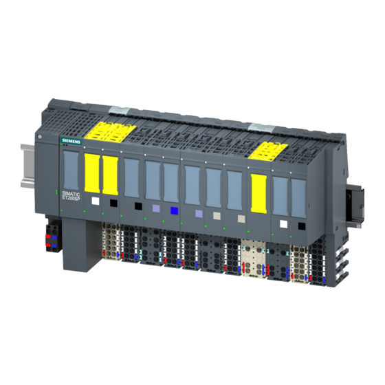
ET 200SP distributed I/O system
SIMATIC
ET 200SP
ET 200SP distributed I/O system
Product Information
Translation of original operating instructions
07/2013
A5E32288220-AA
___________________
Preface
___________________
Product overview
___________________
Application planning
___________________
Installation
___________________
Connecting
___________________
Configuring
___________________
Maintenance
___________________
Technical specifications
___________________
Accessories/spare parts
1
2
3
4
5
6
7
8
Advertisement
Table of Contents

Related Manuals for Siemens ET 200SP distributed I/O system


Summarization of Contents
Preface
Scope of the product information
Details the scope and purpose of this product information document concerning fail-safe modules.
Product overview
What are fail-safe automation systems and fail-safe modules?
Explains fail-safe automation systems and the characteristics of fail-safe modules.
Achievable safety classes
Outlines the safety classes (SIL, Performance Level) achievable with fail-safe modules.
Use in SIMATIC Safety F-systems
Describes how ET 200SP fail-safe modules are utilized within SIMATIC Safety F-systems.
Application planning
Introduction
Introduces the configuration possibilities for ET 200SP with fail-safe and non-fail-safe modules.
Assembly example for ET 200SP with fail-safe and non-fail-safe modules
Provides an example configuration of mixed fail-safe and non-fail-safe modules.
Installation
Basics
Covers fundamental installation requirements for ET 200SP fail-safe modules.
Connecting
Safe functional extra-low voltage (SELV) for fail-safe modules
Specifies the requirement for safe functional extra-low voltage (SELV) for fail-safe modules.
Power supply requirements for compliance with NAMUR recommendations
Details power supply requirements adhering to NAMUR recommendations.
Requirements of sensors and actuators for fail-safe modules
Details qualifications and specifications for sensors and actuators used with fail-safe modules.
Capacitive crosstalk of digital input/output signals
Addresses potential errors caused by capacitive crosstalk and their remedies.
Configuring
Assigning the F-destination address for fail-safe modules
Explains the procedure for assigning the F-destination address to fail-safe modules.
Maintenance
Firmware update
Describes the process and requirements for updating the firmware of fail-safe modules.
Technical specifications
Protecting ET 200SP with fail-safe modules against overvoltages
Provides recommendations for protecting ET 200SP fail-safe modules from overvoltages.
Standards and approvals
Lists the EC directives and harmonized European Standards the system complies with.
Accessories/spare parts
Lightning protection and overvoltage protection for fail-safe modules
Discusses overvoltage suppressors and protection components for fail-safe modules.
Components for overvoltage protection of fail-safe modules (lightning protection zone transition 0s to 1)
Lists specific overvoltage arresters for fail-safe modules, including article numbers.
Glossary
1001 evaluation
Defines sensor evaluation where one sensor has a 1-channel connection.
1002 evaluation
Defines sensor evaluation using two input channels for comparison.
Acknowledgment time
Time for F-I/O to acknowledge the sign of life from the F-CPU.
Actuator
Devices that switch loads, like relays or solenoid valves.
Availability
Probability that a system is functional at a specific point in time.
Channel fault
Channel-specific fault, such as wire break or short circuit.
Channel group
Grouping of module channels for parameter assignment.
Channel number
Unique identifier for module inputs/outputs for diagnostics.
Channel-specific passivation
Passivation of only the affected channel in case of a channel fault.
CRC
Cyclic Redundancy Check for data validation.
CRC signature
Validates process values and parameters using a CRC check.
Dark period
Brief deactivation of output during test cycles.
Derating
Refers to temperature characteristics.
Discrepancy analysis
Analysis to prevent errors from time differences in input signals.
Discrepancy time
Configurable time for discrepancy analysis.
F-CPU
Central processing unit with fail-safe capability in SIMATIC Safety.
F-I/O
Collective name for fail-safe inputs and outputs in SIMATIC Safety.
Fail-safe modules
ET 200SP modules with integrated safety functions for safety-related operation.
Fail-safe systems
Systems that remain in or assume a safe state upon failure.
Fault response time
Interval between a fault occurrence and a safe reaction.
Fault tolerance time
Time a process can be left unattended without risk.
F-monitoring time
Monitoring time for safety-related communication.
F-Systems
Fail-safe automation systems.
Module fault
External or internal faults affecting a module.
Monitoring time
Refers to PROFIsafe monitoring time.
M-switch
Part of fail-safe digital output for current sinking.
Nonequivalent sensor
Sensor connected via 2 channels for fail-safe systems.
Passivation
Switching channels to a safe state due to detected faults.
Performance Level
Safety rating according to ISO 13849-1.
PROFIsafe
Safety-oriented PROFINET I/O bus profile.
PROFIsafe address
Address configured for each fail-safe module.
PROFIsafe monitoring time
Monitoring time for safety-related communication between F-CPU and F-I/O.
Proof-test interval
Period after which a component must be forced to fail-safe state.
P-switch
Part of fail-safe digital output for current sourcing.
Redundancy, availability-enhancing
Use of multiple components to maintain functionality during faults.
Redundancy, safety-enhancing
Multiple component availability for exposing hardware faults.
Reintegration
Process of switching from fail-safe to process values after fault elimination.
Safe state
The basic principle of the safety concept in F-systems.
Safety class
Safety Integrity Level (SIL) according to IEC 61508.
Safety function
Mechanism enabling fail-safe operation within SIMATIC Safety.
Safety message frame
Frame used for transferring data in safety mode.
Safety mode
Operating mode for safety-related communication.
Safety program
Safety-related user program.
Safety-related communication
Communication for exchanging fail-safe data.
Sensor evaluation
Methods for reading and comparing sensor signals.
Sensors
Devices for accurate detection of digital and analog signals.
SIL
Safety Integrated Level, synonymous with safety class.
Standard mode
Operating mode for standard communication, not safety-related.
Value status
Binary information on the validity of a digital signal.
Need help?
Do you have a question about the ET 200SP distributed I/O system and is the answer not in the manual?
Questions and answers