Table of Contents
Advertisement
Assisting the automation
industry since 1986
User manual
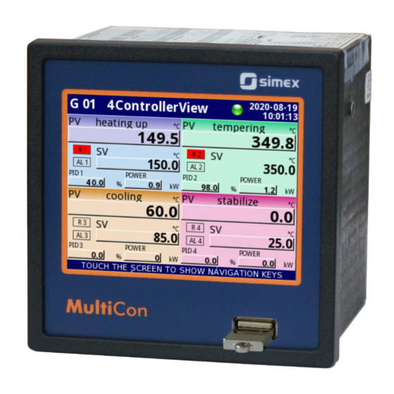
CONTROLLER/DATA RECORDER
MultiCon CMC-99/141
Firmware: v.2.27.0 or higher
•
Read the user's manual carefully before starting to use the unit or software.
Producer reserves the right to implement changes without prior notice.
2016.06.01
MultiCon CMC-99/141_INSSXEN_v.1.17.015
Advertisement
Table of Contents

Related Manuals for Simex multicon cmc-141


Summarization of Contents
1. BASIC REQUIREMENTS AND USER SAFETY
1.1. THE USE OF TOUCH-SCREEN
Guidelines for proper operation of the touch-sensitive display to avoid damage.
4. DEVICE INSTALLATION
4.3. CONNECTION METHOD
Details on how to properly connect power supply and measurement signals to the device's terminals.
5. INTRODUCTION TO MultiCon CMC-99/141
5.2. HARDWARE CONFIGURATIONS
Explains the modular design with base unit, optional I/O, and communication modules.
6. WORKING WITH THE MultiCon CMC-99/141
6.1. MultiCon CMC-99/141 POWER UP
Describes the startup sequence, including the logo, OS loading, and software version display.
6.3. DISPLAY
Details the TFT screen, touch panel, and user interface elements for operation.
7. CONFIGURATION OF THE MultiCon CMC-99/141
7.5. DEVICE CONFIGURATION
The main menu for configuring all device inputs and outputs for system control.
7.8. LOGICAL CHANNELS
Defines and configures logical channels, used as data sources for outputs, controllers, or other channels.
7.13. CONTROLLERS
Details on configuring PID controllers for advanced actuator control.
7.15. MODBUS
Configuration settings for Modbus communication protocol, including Master and Slave modes.
7.17. ACCESS OPTIONS
Covers single-level and multi-level access protection, password management, and user permissions.
8. APPENDICES
8.1. PS3, PS4, PS32, PS42 - POWER SUPPLY MODULE
Technical data for various power supply modules compatible with the device.
8.2. UI4, UI8, UI12, U16, U24, I16, I24 – VOLTAGE AND CURRENT MEASUREMENT MODULES
Technical specifications for voltage and current measurement modules.
8.3. UI4N8, UI4D8, UI8N8, UI8D8 – MIXED UIN/UID MODULES
Technical data for mixed universal input/output modules.
8.15. COMMUNICATION MODULES
Technical data for ACM, ETU, and USB communication modules.
8.17. DATA FORMAT
Explains the fixed text format for data obtained from the device.
Need help?
Do you have a question about the multicon cmc-141 and is the answer not in the manual?
Questions and answers