Table of Contents
Advertisement
Assisting the automation
industry since 1986
User manual
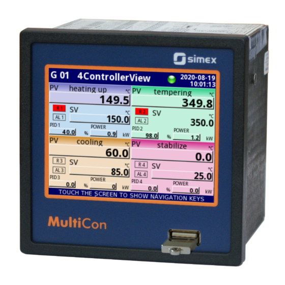
CONTROLLER/DATA RECORDER
MultiCon CMC-99/141
Firmware: v.2.27.0 or higher
•
Read the user's manual carefully before starting to use the unit or software.
Producer reserves the right to implement changes without prior notice.
2016.06.01
MultiCon CMC-99/141_INSSXEN_v.1.17.015
Advertisement
Table of Contents

Subscribe to Our Youtube Channel
Related Manuals for Simex multicon cmc-99


Summary of Contents for Simex multicon cmc-99
- Page 1 Assisting the automation industry since 1986 User manual CONTROLLER/DATA RECORDER MultiCon CMC-99/141 Firmware: v.2.27.0 or higher • Read the user's manual carefully before starting to use the unit or software. Producer reserves the right to implement changes without prior notice.
-
Page 2: Table Of Contents
User Manual For - CONTROLLER/DATA RECORDER MultiCon CMC-99/141 CONTENTS 1. BASIC REQUIREMENTS AND USER SAFETY..................5 1.1. THE USE OF TOUCH-SCREEN.......................6 2. GENERAL CHARACTERISTICS.......................6 3. TECHNICAL DATA............................9 4. DEVICE INSTALLATION.........................10 4.1. UNPACKING...........................11 4.2. ASSEMBLY.............................12 4.3. CONNECTION METHOD.......................14 4.3.1. Available modules........................17 4.4. - Page 3 User Manual For - CONTROLLER/DATA RECORDER MultiCon CMC-99/141 other channel for FT4 module...................135 7.9. BUILT-IN INPUTS.........................137 7.9.1. Built-in inputs - General settings..................137 7.9.2. Built-in inputs - Input modules.....................139 7.9.3. Built-in inputs - Binary input Inp.X2 : Digital 24V..............139 7.9.4. Built-in inputs - Demo input numbered X3, X4, X5..............140...
- Page 4 User Manual For - CONTROLLER/DATA RECORDER MultiCon CMC-99/141 7.15.2.4. Modbus SLAVE - List of registers..............207 7.15.2.5. Modbus SLAVE - Transmission errors handling..........209 7.15.2.6. Modbus SLAVE- Example of query/answer frames..........209 7.15.3. Modbus - MASTER mode....................210 7.15.3.1. Modbus MASTER - Device templates parameter block........211...
-
Page 5: Basic Requirements And User Safety
User Manual For - CONTROLLER/DATA RECORDER MultiCon CMC-99/141 Explanation of symbols used in the manual: - This symbol denotes especially important guidelines concerning the installation and operation of the device. Not complying with the guidelines denoted by this symbol may cause an accident, damage or equipment destruction. -
Page 6: The Use Of Touch-Screen
(for example the stylus delivered with the device). The display of the MultiCon CMC-99/141 should also be protected against aggressive substances and extremely high and low temperatures (see Chapter 3. - Page 7 • Full freedom of data sources, presentation modes and controlling methods The multi level structure of the MultiCon CMC-99/141 firmware allows for selection of presented data sources, presentation modes and controlling methods. The MultiCon CMC-99/141 displays the values of virtual logical channels which can be fed with: –...
- Page 8 User Manual For - CONTROLLER/DATA RECORDER MultiCon CMC-99/141 Build-in analog input Buid-in binary input External input (RS-485) Profiles/timers Controller Mathematical & logical combination data States of hardware & virtual outputs Set point values Interface Numeric, logical or text values Reading data via Ethernet Charts &...
-
Page 9: Technical Data
User Manual For - CONTROLLER/DATA RECORDER MultiCon CMC-99/141 3. TECHNICAL DATA Power supply voltage 85...230...260V AC/DC; 50 ÷ 60 Hz (depending on version) or 19... 24 ...50V DC; 16V... 24 ...35V AC External Fuse (required) T - type, max. 2 A Power consumption typically 15 VA;... -
Page 10: Device Installation
User Manual For - CONTROLLER/DATA RECORDER MultiCon CMC-99/141 Housing dimensions 96 x 96 x 100 mm (small housing - 3,5” Display) or 144 x 144 x 100 mm (big housing - 5,7” Display) Mounting hole 90.5 x 90.5 mm (small housing - 3,5” Display) or 137 x 137 mm (big housing - 5,7”... -
Page 11: Unpacking
Attached with the unit please find: – assembly brackets - 2 pieces, – pointer for touch screen, user’s manual for MultiCon CMC-99/141 unit (device) in pdf. , –... -
Page 12: Assembly
User Manual For - CONTROLLER/DATA RECORDER MultiCon CMC-99/141 4.2. ASSEMBLY - The unit is designed for mounting inside housings (control panel, switchboard) insuring appropriate protection against surges and interference. Metal housings must be connected to ground in a way that complies with the governing regulations. - Page 13 User Manual For - CONTROLLER/DATA RECORDER MultiCon CMC-99/141 96 x 96 housing: H, W = 115 mm 144 x 144 housing: H, W = 165 mm Fig. 4.3. Minimum distances when assembly of a number of units 98 mm removable terminals 8 mm Fig.
-
Page 14: Connection Method
User Manual For - CONTROLLER/DATA RECORDER MultiCon CMC-99/141 To avoid connectors slots destruction use the method shown on Fig. 4.5 GOOD back side of device connector WRONG back side of device connector Fig. 4.5. Connectors removing method 4.3. CONNECTION METHOD Caution - Installation should be conducted by qualified personnel. - Page 15 User Manual For - CONTROLLER/DATA RECORDER MultiCon CMC-99/141 - Tighten the clamping screws. The recommended tightening torque is 0.5 Nm. Loose screws can cause fire or defective operation. Over tightening can lead to damaging the connections inside the units and breaking the thread.
- Page 16 User Manual For - CONTROLLER/DATA RECORDER MultiCon CMC-99/141 Connections of power supply voltage and measurement signals are executed using the screw connections on the back of the unit’s housing. 5-6 mm Fig. 4.7. Method of cable isolation replacing and cable terminals dimensions...
-
Page 17: Available Modules
User Manual For - CONTROLLER/DATA RECORDER MultiCon CMC-99/141 If the UN3 or UN5 module is installed, the +24V DC output is available only in – devices equipped with PS42 power supply module. In other cases there is no +24V DC output available and these terminals remain disconnected. - Page 18 User Manual For - CONTROLLER/DATA RECORDER MultiCon CMC-99/141 UI12 12 current 24 current inputs 24 voltage inputs + 12 voltage inputs IN10 IN10 IN10 IN11 IN11 IN11 IN12 IN12 IN12 IN13 IN13 IN13 IN14 IN14 IN14 IN15 IN15 IN15 IN16...
- Page 19 User Manual For - CONTROLLER/DATA RECORDER MultiCon CMC-99/141 UI4N8 UI4D8 UI8N8 UI8D8 8 resistance 4 current and 4 voltage 8 resistance 8 current and voltage + 4 current and 4 voltage inputs + 8 digital inputs + 8 current and voltage inputs...
- Page 20 User Manual For - CONTROLLER/DATA RECORDER MultiCon CMC-99/141 6 isolated current input IN 1 IN 2 IN 3 IN 4 IN 5 IN 6 Fig. 4.12.Isolated current input modules...
- Page 21 User Manual For - CONTROLLER/DATA RECORDER MultiCon CMC-99/141 2 flowmeter inputs 2 pulse inputs 4 flowmeter inputs 4 pulse inputs + 2 current inputse + 4 current inputs + 2 current inputs + 4 current inputs Inp11 Inp11 Inp12 Inp12...
- Page 22 User Manual For - CONTROLLER/DATA RECORDER MultiCon CMC-99/141 TC12 8 thermocouple inputs 12 thermocouple inputs 4 thermocouple inputs IN_T IN_T IN_T IN10 IN11 IN12 Fig. 4.14. TC input modules...
- Page 23 User Manual For - CONTROLLER/DATA RECORDER MultiCon CMC-99/141 6 RTD inputs 4 RTD inputs Fig. 4.15. RTD input modules...
- Page 24 User Manual For - CONTROLLER/DATA RECORDER MultiCon CMC-99/141 3 universal inputs 5 universal inputs V, mA V, mA TC, mV TC, mV V, mA V, mA TC, mV TC, mV V, mA V, mA TC, mV TC, mV V, mA...
- Page 25 User Manual For - CONTROLLER/DATA RECORDER MultiCon CMC-99/141 8 Digital inputs 16 Digital inputs 24 Digital inputs IN17 IN25 COM 1-4 IN11 COM 1-4 COM 1-4 IN10 IN18 IN26 COM 5-8 COM 5-8 IN21 COM 5-8 IN10 IN10 IN27 IN19...
- Page 26 User Manual For - CONTROLLER/DATA RECORDER MultiCon CMC-99/141 2 universal counters 4 universal counters 2 hourmeters 4 hourmeters Inp11 Inp11 START/STOP 1 START/STOP 1 Inp12 Inp12 PRG 1 PRG 1 Prg1 Counter 1 Prg1 Counter 1 COM 1 COM 1...
- Page 27 User Manual For - CONTROLLER/DATA RECORDER MultiCon CMC-99/141 8 SSR outputs 16 SSR outputs 24 SSR outputs +10..24V DC +10..24V DC +10..24V DC OUT1 OUT1 OUT1 OUT2 OUT2 OUT2 OUT3 OUT3 OUT3 OUT4 OUT4 OUT4 OUT5 OUT5 OUT5 OUT6 OUT6...
- Page 28 User Manual For - CONTROLLER/DATA RECORDER MultiCon CMC-99/141 4 relay outputs 5A/250V 8 relay outputs 1A/250V OUT1 OUT1 6 relay outputs 5A/250V R121 12 relay outputs 1A/250V OUT2 OUT1 OUT1 OUT2 OUT3 OUT2 OUT2 OUT3 OUT4 OUT3 OUT5 OUT6 OUT3...
- Page 29 User Manual For - CONTROLLER/DATA RECORDER MultiCon CMC-99/141 2 current output 4 current output 6 current output 8 current output OUT 4 OUT 6 OUT 8 OUT 3 OUT 5 OUT 7 OUT 2 OUT 2 OUT4 OUT6 OUT 1...
- Page 30 User Manual For - CONTROLLER/DATA RECORDER MultiCon CMC-99/141 host host host RJ-45 RJ-45 Fig. 4.22. Communication Modules RS232/RS485 or USB/RS485 interface Fig. 4.23. Connection of RS-485 transmission signals The MultiCon CMC-99/141 device supports the following converters: USB / RS-485 converter SRS-USB/4-Z45 –...
-
Page 31: Maintenance
The main difference is the concept of using Logical Channels as a bridge: physical inputs and outputs - visualisation and controlling processes. Designers of MultiCon CMC-99/141 decided to use such solution to increase functionality of the device and make software near fully independent on the hardware. -
Page 32: Logical Channels
User Manual For - CONTROLLER/DATA RECORDER MultiCon CMC-99/141 5.1.1. Logical channels A Logical Channel is a data stream existing in the memory of the device, having it's own name and can be displayed in almost any way. Logical Channels can be used as: –... - Page 33 – measurement data from built-in physical input channels, – output data and states of physical output channels, output data and states of external modules connected to MultiCon CMC-99/141 via – RS-485 interface, – states and data coming from outputs of controlling processes, –...
-
Page 34: Groups
To make visualization clearer Logical Channels can be gather into Groups. 5.1.2. Groups A Group is a set of 1-6 Logical Channels. The MultiCon CMC-99/141 can show on the same screen only channels belonging to the same Group, additionally each Group has its own individual name making operation with the device very clear. -
Page 35: Hardware Configurations
User Manual For - CONTROLLER/DATA RECORDER MultiCon CMC-99/141 5.2. HARDWARE CONFIGURATIONS The functionality of MultiCon CMC-99/141 can fit to the user's needs. The base of the MultiCon CMC-99/141 contains: the main processor, display with touch-screen, Switch Mode Power Supply (in one of two versions: and 85V..230..260V... -
Page 36: Working With The Multicon Cmc-99/141
6.3. DISPLAY The MultiCon CMC-99/141 displays all data and dialogue on a 3,5” or 5,7” 320x240 pixel, color TFT screen with embedded touch screen panel. New devices have the display protected with a thin transparent plastic cover. This protective layer should be removed before use to ensure perfect visibility of pictures and sensitivity of the touch-screen. -
Page 37: Information Bar
Data panels Chapter 6.3.3 Navigation bar Chapter 6.3.2 Fig. 6.1. Typical view of a MultiCon CMC-99/141 main page, after touching display 6.3.1. Information bar The Information bar informs the user about current, display group, logging, actual date and time. name of the group which is visible on the display... -
Page 38: Navigation Bar
User Manual For - CONTROLLER/DATA RECORDER MultiCon CMC-99/141 yellow color – It is possible to log data in the device but there is less than 20% • of total free memory remaining (to clear the memory you need to move onto a... -
Page 39: Data Panels
User Manual For - CONTROLLER/DATA RECORDER MultiCon CMC-99/141 To enter directly into the configuration menu of particular Logical channel , press and hold screen over the channel data panel for 3-4 seconds (see option (1) in the Fig. 6.4 entering configuration of the logical channel named 'Temperature' ). - Page 40 User Manual For - CONTROLLER/DATA RECORDER MultiCon CMC-99/141 Fig. 6.5. View of the Data panel In all data panels (a sample of a data panel is shown inside the frame marked (1) in Fig. 6.5) the following information is available: value of the logical channel (denoted by (2) in Fig.
- Page 41 User Manual For - CONTROLLER/DATA RECORDER MultiCon CMC-99/141 Fig. 6.7. Examples of Horizontal (for 3 channels) and Vertical Bars (for 5 channels) Fig. 6.8. Examples of Horizontal (for 3 channels) and Vertical Charts (for 5 channels) Fig. 6.9 Examples of Phasor Charts presentation mode...
-
Page 42: Important Messages
User Manual For - CONTROLLER/DATA RECORDER MultiCon CMC-99/141 Index of displayed groups Inactive logical channels in the groups . . . Group Fig. 6.11. Examples of simultaneous presentation of Many Groups There is also the possibility to show many groups on a single screen (Fig. 6.11). In this mode channels belonging to the same group are displayed under one another, and groups are placed side by side. -
Page 43: Configuration Of The Multicon Cmc-99/141
User Manual For - CONTROLLER/DATA RECORDER MultiCon CMC-99/141 7. CONFIGURATION OF THE MultiCon CMC-99/141 7.1. EDIT DIALOGUES Configuration process are based on edit dialogues. Some of the dialogues are common to different menus, such dialogues are: – text editor, which is divided into tabs: letters, see Fig. - Page 44 User Manual For - CONTROLLER/DATA RECORDER MultiCon CMC-99/141 Fig. 7.5. Text editor – font and background Fig. 7.6. Value editor – decimal form color selection Fig. 7.7. Value editor – hexadecimal form Fig. 7.8. Value editor – binary form Fig. 7.9. Single choice type editor Fig.
- Page 45 User Manual For - CONTROLLER/DATA RECORDER MultiCon CMC-99/141 Functions of common buttons “ Exit ” - exits from current menu or sub-menu ”OK” - accept choice or changes of edit dialogue (and exit from this dialogue) “Cancel” - reject entered choice or changes of edit dialogue (and exit from this dialogue) Selection of element for editing.
-
Page 46: Main Menu Selection Panel
User Manual For - CONTROLLER/DATA RECORDER MultiCon CMC-99/141 7.2. MAI N MENU SELECTION PANEL Pressing the [MENU] button on the Navigation bar (see Chapter 6.3.2. Navigation bar ) enters the main selection panel (see Fig. 7.13 ). This panel allows users to select between entering the Device Configuration menu, Files management menu and Device Information window. -
Page 47: Files Management
User Manual For - CONTROLLER/DATA RECORDER MultiCon CMC-99/141 7.3. FILES MANAGEMENT Fig. 7.15. This button allows to entry to the files management menu After pressing MENU -> Files management (see Fig. 7.15 ) opens the files management menu which is used to exchange data with a flash drive. - Page 48 User Manual For - CONTROLLER/DATA RECORDER MultiCon CMC-99/141 Fig. 7.17. Logging files menu The Logging files menu is presented in Fig. 7.17 . The menu consists of buttons: Export files - after pressing this button the selected logged files will be exported to a –...
- Page 49 User Manual For - CONTROLLER/DATA RECORDER MultiCon CMC-99/141 In Fig. 7.18 presents a sample view of selected logged files from Group 1. The numbers refer – (1) - group number, – (2) - the selected logged file, – (3) - no description for the logged file, –...
- Page 50 User Manual For - CONTROLLER/DATA RECORDER MultiCon CMC-99/141 Files management: The second button on the File management menu is the Configuration files button. Pressing this button, will open the menu shown in Fig. 7.20 , which allows the user to load/save the configuration and Modbus templates.
- Page 51 User Manual For - CONTROLLER/DATA RECORDER MultiCon CMC-99/141 Load/save Modbus slave templates allows the user to load/save the configuration of the Modbus SLAVE protocol with a defined block of registers, e.g.: register type (Holding/Input), write mode of register, data format (16 bits or 32 bits). For configuration of Modbus SLAVE see Chapter 7.15.2.
- Page 52 User Manual For - CONTROLLER/DATA RECORDER MultiCon CMC-99/141 In this menu Administrator has access to two buttons: Load configuration and Save configuration (see Fig. 7.23) which allows to store and move saved access settings using external USB flash drive. That streamlines the process of setting up another devices. It is the only way to save Access options settings (see Chapter 7.17.
-
Page 53: Device Information, Licence, Firmware Update, Remote Display, Export Manual And Renew Configuration
User Manual For - CONTROLLER/DATA RECORDER MultiCon CMC-99/141 7.4. DEVICE INFORMATION, LICENCE, FIRMWARE UPDATE, REMOTE DISPLAY, EXPORT MANUAL AND RENEW CONFIGURATION Fig. 7.24. The button which will show information about the device The Device information menu gives basic information about the device and allows the user to enter a licence key for data logging, perform a firmware update of the device, run displaying on the remote screen and download a user manual to the flash drive. - Page 54 User Manual For - CONTROLLER/DATA RECORDER MultiCon CMC-99/141 Note on the update: – do not power off the device or remove the flash drive from the USB port during the update, – the update process must go continuously to the end, the user will be informed of the progress throughout the update cycle;...
- Page 55 User Manual For - CONTROLLER/DATA RECORDER MultiCon CMC-99/141 To establish connection between the device and PC, port number 6000 must be unlocked in software and hardware firewall. The Export manual button allows you to download the user manual on to the flash drive.
-
Page 56: Device Configuration
User Manual For - CONTROLLER/DATA RECORDER MultiCon CMC-99/141 7.5. DEVICE CONFIGURATION Fig. 7.28. The device configuration menu The Device configuration menu is the main menu of the device that allows the user to configure all inputs and outputs of the device to measure and control the system. - Page 57 User Manual For - CONTROLLER/DATA RECORDER MultiCon CMC-99/141 Chapter 7.7 Chapter 7.8 Chapter 7.9 Chapter 7.10 Chapter 7.11 Chapter 7.12 Chapter 7.13 Chapter 7.14 Chapter 7.15 Chapter 7.16 Chapter 7.17 Chapter 7.18 Chapter 7.19 Fig. 7.29. Main menu selection panel...
- Page 58 User Manual For - CONTROLLER/DATA RECORDER MultiCon CMC-99/141 Fig. 7.31. Warning message about unsaved configuration Fig. 7.32. Example of unsaved configuration screen view...
-
Page 59: Configuration Menu Structure
User Manual For - CONTROLLER/DATA RECORDER MultiCon CMC-99/141 7.6. CONFIGURATION MENU STRUCTURE Basic General settings Display mode Language Displayed group Date and time Input channels Display time Reg.num. display. Add a new view LCD screen Delete this view Backlight Move to pos. - Page 60 User Manual For - CONTROLLER/DATA RECORDER MultiCon CMC-99/141 Decay constant Name Name Unit Source = analog input Input unit Unit Mode Scaling = linear Base unit Output unit Wire compensation Mode = Hardwaer input Compensation mode Mode Source Point 1...
-
Page 61: Settings
User Manual For - CONTROLLER/DATA RECORDER MultiCon CMC-99/141 Name Months Group Display option Triggering mode Days Name Triggering source Week days Bars Triggering times Hours Charts Pause mode Minutes Line width Seconds Pause source Profiles/times Time scale Idle value Background... - Page 62 User Manual For - CONTROLLER/DATA RECORDER MultiCon CMC-99/141 Device type Load device templ. Channel value Register type Device name Value register Device templates Write mode Decimal point Mode Load device templ. Register number Dec.point register Baud rate Save device templ.
-
Page 63: General Settings
User Manual For - CONTROLLER/DATA RECORDER MultiCon CMC-99/141 7.7. GENERAL SETTINGS MENU Device configuration General settings Logical channels Built-in inputs Built-in outputs External outputs Profiles/timers Controllers Groups Modbus Network settings Access options Printouts Notifications The General settings menu allows to configure user interface display settings, the default screen when the device powers on and automatic view change settings. - Page 64 User Manual For - CONTROLLER/DATA RECORDER MultiCon CMC-99/141 disabled - this option turns off screen savers, the LCD screen is illuminated ◦ at all times according to parameter settings: Backlight (see above Screen saver parameter block ) 1min, 5min, 10min, 30min, ◦...
- Page 65 User Manual For - CONTROLLER/DATA RECORDER MultiCon CMC-99/141 CSV Format settings parameter block – contains parameters which are related with – creating and sending CSV files, • Decimal separator – selects decimal separator in CSV files for numeric values, ◦...
- Page 66 User Manual For - CONTROLLER/DATA RECORDER MultiCon CMC-99/141 Example: Steps to create four views are as follows: In the Change mode parameter select detailed list, Press the Setup list button and enter the View menu, Set parameters for a first View, Arrows placed in the upper right corner of the screen allow you to move to the next view.
-
Page 67: Logical Channels
User Manual For - CONTROLLER/DATA RECORDER MultiCon CMC-99/141 7.8. LOGICAL CHANNELS General settings MENU Device configuration Logical channels Built-in inputs Built-in outputs External outputs Profiles/timers Controllers Groups Modbus Network settings Access options Printouts Notifications The Logical channels menu is used to configure the logical channels. Channels can be treated as input data for outputs, controllers or other Logical channels and can be collected into Groups for simultaneous display. - Page 68 User Manual For - CONTROLLER/DATA RECORDER MultiCon CMC-99/141 The channel for Mode=disabled has only one parameter - the name of the channel. In other modes the Logical channels are active and may affect the processing and control data. Parameters and blocks of parameters common for active Logical channels: –...
- Page 69 User Manual For - CONTROLLER/DATA RECORDER MultiCon CMC-99/141 Processing parameter block For this block the parameters are: – Scaling , – Filter type, To enter the scaling menu press the button next to the Scaling label. The menu has the following options: a) disabled –...
- Page 70 User Manual For - CONTROLLER/DATA RECORDER MultiCon CMC-99/141 Lets assume that our temperature range is from -50˚C to 85˚C (but this range is arbitrary). In that case: Scale parameter set as linear , – – enter Configure scaling submenu: in Output unit parameter write: ˚F , •...
- Page 71 User Manual For - CONTROLLER/DATA RECORDER MultiCon CMC-99/141 Num. of point – read only parameter, in displays number of points that ◦ currently are defined in characteristic, ◦ Edit points – submenu that defines point in characteristic: – Input value – point value before scaling, –...
- Page 72 User Manual For - CONTROLLER/DATA RECORDER MultiCon CMC-99/141 Example: Steps to create a user characteristic consisting of 6 points (like on Fig. 7.34): Press the button next to the Scaling label and select user characteristic option (point (1) and (2) in Fig. 7.35).
- Page 73 User Manual For - CONTROLLER/DATA RECORDER MultiCon CMC-99/141 When the user wants to add a new point between the existing point e.g. between 5 and 6, select the edit Point 5 and then add a new point by press the Add point button.
- Page 74 User Manual For - CONTROLLER/DATA RECORDER MultiCon CMC-99/141 peak detect – function which allows to detect and visualize peak values in measured – signal. Detection of the peak value can be done if the measured signal raises and drops (or the opposite) by value, which is settable by the user. Next, the detected value can be hold for settable by user period of time.
- Page 75 User Manual For - CONTROLLER/DATA RECORDER MultiCon CMC-99/141 Displaying parameter block The constant parameters of Displaying block are: Format - the logical channel data formats, which are: – numeric – value in this channel is displayed as a number, •...
- Page 76 User Manual For - CONTROLLER/DATA RECORDER MultiCon CMC-99/141 Example of a number representing the value of the logical channel: part 1 of 3 part 2 of 3 part 3 of 3 part 1 of 2 part 2 of 2 all digits (limited ability to display up to...
- Page 77 User Manual For - CONTROLLER/DATA RECORDER MultiCon CMC-99/141 Fig. 7.39. Input channels menu – 2 different kinds of Displaying parameters To calculate percentage which will be displayed on the indicator, the device is using following equation: V −Lo ⋅100 % Hi−Lo...
- Page 78 User Manual For - CONTROLLER/DATA RECORDER MultiCon CMC-99/141 Channel highlight – block of parameters, used to change background color – and its mode in the logical channel. User can set up to three different variants of highlights, depending to event weight, which should trigger highlight in this channel.
- Page 79 User Manual For - CONTROLLER/DATA RECORDER MultiCon CMC-99/141 Fig. 7.41 Color edit dialog Comments regarding the display: – The precision of the displayed data can be set in the device with any accuracy (up to 4 decimal places), it must be remembered that the resolution and accuracy of external sensors connected to the device is finite, and usually not better than 0.1%.
- Page 80 User Manual For - CONTROLLER/DATA RECORDER MultiCon CMC-99/141 Logical channel 2: Overhead alarm threshold: In Name parameter write: Overhead alarm threshold, – Mode parameter set as: Set point value , – Edit button parameter set as: enabled, – In Unit parameter write: mA , –...
- Page 81 User Manual For - CONTROLLER/DATA RECORDER MultiCon CMC-99/141 Example 2: Task: User's task is to set blinking highlight on temperature channel, which will be activated on three different levels. Solution: After connecting all measuring devices and configuring them in MultiCon, we can start to configure the highlights.
- Page 82 User Manual For - CONTROLLER/DATA RECORDER MultiCon CMC-99/141 Source X parameter set as logical channel where the temperature • measurement is shown, Type of source Y parameter set as: channel , • Source Y parameter set as logical channel named as First level, •...
- Page 83 User Manual For - CONTROLLER/DATA RECORDER MultiCon CMC-99/141 Highlight color parameter set as: 2 , • ◦ Mode parameter set as: blinking, ◦ In Blink period parameter write: 3 , ◦ In Trig.hold time parameter write: 3, ◦ Trigger parameter set as logical channel named Calc. Second level , ◦...
-
Page 84: Logical Channels - Hardware Input Mode
User Manual For - CONTROLLER/DATA RECORDER MultiCon CMC-99/141 7.8.2. Logical channels - Hardware input mode disabled Mode MENU Device configuration Logical channel Hardware input Hardware output monitor Modbus Set point value Math function Controller Profile/timer Profile/timer (cycle counter) Data from other channel This mode allows the user to measure data from installed input modules which can be displayed, and/or processed in any other logical channels (e.g. - Page 85 User Manual For - CONTROLLER/DATA RECORDER MultiCon CMC-99/141 Slot A, Input 1 see Fig. 4.8 I16 Module 16 current inputs Slot X (built-in slot) Built-in binary input Input 4 Built-in Demo input Fig. 7.42. The view of a sample list of available hardware inputs for a device...
- Page 86 User Manual For - CONTROLLER/DATA RECORDER MultiCon CMC-99/141 Fig. 7.43. Change source configuration for different types of modules b) built-in digital input is always designated as Inp.X2: Digital 24V The device has a built-in digital input, which can be used, for example as a switch for a process.
-
Page 87: Logical Channels - Hardware Output Monitor Mode
User Manual For - CONTROLLER/DATA RECORDER MultiCon CMC-99/141 7.8.3. Logical Channels - Hardware output monitor mode disabled Hardware input Mode Hardware output monitor MENU Device configuration Logical channel Modbus Set point value Math function Controller Profile/timer Profile/timer (cycle counter) Data from other channel This mode allows the user to display data from built-in output modules, processed in any other logical channels (e.g. - Page 88 User Manual For - CONTROLLER/DATA RECORDER MultiCon CMC-99/141 Fig. 7.44. Input channels menu – parameters specific for Hardware Output Monitor mode Source parameter in the Hardware output monitor mode After pressing Source, a list of available hardware outputs appears. The selected option will be the source of data for that logical channel.
-
Page 89: Logical Channels - Modbus Mode
User Manual For - CONTROLLER/DATA RECORDER MultiCon CMC-99/141 7.8.4. Logical Channels - Modbus mode disabled Hardware input Hardware output monitor Mode MENU Device configuration Logical channel Modbus Set point value Math function Controller Profile/timer Profile/timer (cycle counter) Date from other channel Modbus mode allows the user to configure the logical channel to: –... -
Page 90: 7.8.1. Logical Channels - General
User Manual For - CONTROLLER/DATA RECORDER MultiCon CMC-99/141 and one ethernet port, which allows for an advanced Multi-Modbus system (see Fig. 7.47). – Slave device - this parameter is only visible if the selected option in the Port parameter is in Modbus MASTER mode (see Chapter 7.15.3. Modbus - MASTER mode ). - Page 91 User Manual For - CONTROLLER/DATA RECORDER MultiCon CMC-99/141 SLAVE Address 1 Reg. N Device Reg. 0 Reg. 0 SLAVE Reg. N Address 1 Device Unit SLAVE Address 2 Reg. N Device Reg. 0 Built-in Advanced Reg. 0 Address 4 SLAVE Reg.
-
Page 92: Logical Channels - Set Point Value Mode
User Manual For - CONTROLLER/DATA RECORDER MultiCon CMC-99/141 7.8.5. Logical Channels - Set point value mode disabled Hardware input Hardware output monitor Modbus Mode MENU Device configuration Logical channel Set point value Math function Controller Profile/timer Profile/timer (cycle counter) Data from other channel In Set point value mode the user defines constant value which can be displayed on the screen, used for calculations in other channels (e.g. -
Page 93: User Manual For - Controller/Data Recorder Multicon Cmc
User Manual For - CONTROLLER/DATA RECORDER MultiCon CMC-99/141 Latch parameter block - allows user to set the latch function which will hold the last – value of a channel (discussed in Chapter 7.8.1. Logical Channels - General settings ), –... - Page 94 User Manual For - CONTROLLER/DATA RECORDER MultiCon CMC-99/141 Manual operation of a button in the data panel Action button in the data panel depends on the parameters from Latch block (description of the Latch parameter block in Chapter 7.8.1. Logical Channels - General settings ) and on the Format parameter in the Displaying parameter block (description of the Displaying parameter block in Chapter 7.8.1.
-
Page 95: Logical Channels - Math Function Mode
User Manual For - CONTROLLER/DATA RECORDER MultiCon CMC-99/141 7.8.6. Logical Channels - Math function mode disabled Hardware input Hardware output monitor Modbus Set point value Mode MENU Device configuration Logical channel Math function Controller Profile/timer Profile/timer (cycle counter) Data from other channel... -
Page 96: 7.8.1. Logical Channels - General
User Manual For - CONTROLLER/DATA RECORDER MultiCon CMC-99/141 Processing parameter block - is used for scaling and filtering of data (discussed in – Chapter 7.8.1. Logical Channels - General settings), Displaying parameter block - for these parameters the user select the format and –... - Page 97 User Manual For - CONTROLLER/DATA RECORDER MultiCon CMC-99/141 Maximal value – available for certain math functions, constant value which will be – maximal value for the function, – Averaging time – available for Function=avarege of X , determines logical channel amount of samples which fits in this time and will be averaged;...
- Page 98 User Manual For - CONTROLLER/DATA RECORDER MultiCon CMC-99/141 rising edge – flip-flop triggers when in selected in Clock source parameter • channel rising edge occurs, • falling edge – flip-flop triggers when in selected in Clock source parameter channel falling edge occurs, R input mode –...
- Page 99 User Manual For - CONTROLLER/DATA RECORDER MultiCon CMC-99/141 Fig. 7.53. Sample configuration of logical channel in Math function mode...
- Page 100 User Manual For - CONTROLLER/DATA RECORDER MultiCon CMC-99/141 Math function Description Example The sum of Source X and Source Y [1] + [2] – The sum of value channel 1 and 2 The subtraction of Source X and [1] - [2] – The subtraction of...
- Page 101 User Manual For - CONTROLLER/DATA RECORDER MultiCon CMC-99/141 Math function Description Example The result = 1 if the value of any set ANY X[i]>Y ANY[1,2,3,4]>[5] – if the of selected channels is greater than value of any set of channel 1,...
- Page 102 User Manual For - CONTROLLER/DATA RECORDER MultiCon CMC-99/141 Math function Description Example arctan(X) Arctangent of Source X value arctan([4]) - arctangent value of channel 4 cot(X) Cotangent of Source X value cot([10]) - cotangent value of channel 10 arccot(X) Arccotangent of Source X value...
- Page 103 User Manual For - CONTROLLER/DATA RECORDER MultiCon CMC-99/141 User should pay attention for a fact that some mathematical functions have limitations. Those limitations are listed bellow: Function X/Y: If Y equals 0 , then logical channel will be in -Err - state;...
- Page 104 User Manual For - CONTROLLER/DATA RECORDER MultiCon CMC-99/141 Function X If X jest is equal 0, and Y is lower than 0, then logical channel will be in • -Err- state; in other way: X==0 Y < 0 ⇒ ERROR If X is lower than 0, and Y is not integer , then logical channel will be in •...
-
Page 105: Logical Channels - Controller Mode
User Manual For - CONTROLLER/DATA RECORDER MultiCon CMC-99/141 7.8.7. Logical Channels - Controller mode disabled Hardware input Hardware output monitor Modbus Set point value Math function Mode MENU Device configuration Logical channel Controller Profile/timer Profile/timer (cycle counter) Data from other channel... -
Page 106: 7.8.1. Logical Channels - General
User Manual For - CONTROLLER/DATA RECORDER MultiCon CMC-99/141 Output Input Multicon Set point value Control Controller system feedback Fig. 7.55. The overall structure of control system implemented in the device Latch parameter block - allows user to set the latch function which will hold the last –... -
Page 107: Logical Channels - Profile/Timer Mode
User Manual For - CONTROLLER/DATA RECORDER MultiCon CMC-99/141 7.8.8. Logical Channels - Profile/timer mode disabled Hardware input Hardware output monitor Modbus Set point value Math function Controller Mode MENU Device configuration Logical channel Profile/timer Profile/timer (cycle counter) Data from other channel... -
Page 108: 7.8.1. Logical Channels - General
User Manual For - CONTROLLER/DATA RECORDER MultiCon CMC-99/141 Latch parameter block - allows the user to set the latch function which will hold the – last value of a channel (discussed in Chapter 7.8.1. Logical Channels - General settings ), –... -
Page 109: Logical Channels - Profile/Timer (Cycle Counter) Mode
User Manual For - CONTROLLER/DATA RECORDER MultiCon CMC-99/141 7.8.9. Logical Channels - Profile/timer (cycle counter) mode disabled Hardware input Hardware output monitor Modbus Set point value Math function Controller Profile/timer Mode MENU Device configuration Logical channel Profile/timer (cycle counter) Data from other channel... -
Page 110: Logical Channels - Data From Other Channel Mode
User Manual For - CONTROLLER/DATA RECORDER MultiCon CMC-99/141 Configure source button in Profile/timer (cycle counter) menu There are two methods for configuring Profiles/timers: – Profiles/timers menu, take following steps: MAIN->Device configuration->Profiles/timers (see Chapter 7.12. PROFILES/TIMERS), – directly in the Logical channel in Profile/timer mode by pressing the Configure source button. -
Page 111: Examples Of Logical Channels Configuration
User Manual For - CONTROLLER/DATA RECORDER MultiCon CMC-99/141 Displaying parameter block - for these parameters the user selects the format and – range of data displayed on the screen (discussed in Chapter 7.8.1. Logical Channels - General settings ), 7.8.11. Examples of Logical Channels configuration 7.8.11.1. - Page 112 User Manual For - CONTROLLER/DATA RECORDER MultiCon CMC-99/141 Scaling parameter set as linear , – press the Configure scaling button, – in Output unit parameter write A , • in Input value parameter in the Point 1 section write 0mA, •...
- Page 113 User Manual For - CONTROLLER/DATA RECORDER MultiCon CMC-99/141 Fig. 7.58. Current and voltage source configuration example...
- Page 114 User Manual For - CONTROLLER/DATA RECORDER MultiCon CMC-99/141 c) For a power, – using the arrows in the top navigation bar, select any logical channel such as 22, – in Name parameter write Power , – Mode parameter set as Math function, –...
- Page 115 User Manual For - CONTROLLER/DATA RECORDER MultiCon CMC-99/141 Fig. 7.59.Math function configuration example In the next step you need to define Group the set up logical channels to view them in one window on the screen. To do this: enter the Group menu and turn it on if its off, –...
- Page 116 User Manual For - CONTROLLER/DATA RECORDER MultiCon CMC-99/141 other parameters in this block - Slot 4, 5, 6 , set as disabled , because we want • to show only three logical channels, – all other parameters should be on default settings, Fig.
- Page 117 User Manual For - CONTROLLER/DATA RECORDER MultiCon CMC-99/141 the Screen saver block parameters set to disabled mode, as in this example we – want to display all the time Backlight with the same clarity, for Initial view block parameters: –...
-
Page 118: Application Of Logical Channel In The Hardware Input Mode For Tc4 Modules
User Manual For - CONTROLLER/DATA RECORDER MultiCon CMC-99/141 7.8.11.2. Application of Logical channel in the Hardware input mode for TC4 modules See also: Appendices 8.6. TC4, TC8, TC12 – THERMOCOUPLE SENSOR MEASUREMENT MODULES and Chapter 7.8.6. Logical Channels - Math function mode. - Page 119 User Manual For - CONTROLLER/DATA RECORDER MultiCon CMC-99/141 in Graph low parameter write -200°C , • in Graph high parameter write 1370°C, • b) For the temperature reading of sensor 2 with the symbol A2: Using the arrows in the top navigation bar, select any Logical channel (except for 1) –...
- Page 120 User Manual For - CONTROLLER/DATA RECORDER MultiCon CMC-99/141 In the next step you need to define Group the set up logical channels to view them in one window on the screen. To do this: – enter the Group menu, to enable the Group 1 if it is off, –...
-
Page 121: Application Of Logical Channel In The Hardware Input Mode For Rt4 Modules
User Manual For - CONTROLLER/DATA RECORDER MultiCon CMC-99/141 7.8.11.3. Application of Logical channel in the Hardware input mode for RT4 modules See also: Appendices 8.7. RT4 , RT6 – RTD MEASUREMENT MODULES. Task: The MultiCon with built-in RT4 module can measure simultaneously temperature at four points. - Page 122 User Manual For - CONTROLLER/DATA RECORDER MultiCon CMC-99/141 – for Display block parameters: • Format parameter set as numeric , • Precision parameter set as 0.0, because Pt1000 sensor precision allows to display its value with one decimal place, in Graph low parameter write 15°C, •...
-
Page 123: Application Of Logical Channel In The Hardware Output Monitor Mode For R45
User Manual For - CONTROLLER/DATA RECORDER MultiCon CMC-99/141 Fig. 7.66. Logical channels configuration - Example 3 7.8.11.4. Application of Logical channel in the Hardware output monitor mode for R45 modules See also: Appendices 8.13. R45, R81, R65, R121 - RELAY MODULES. - Page 124 User Manual For - CONTROLLER/DATA RECORDER MultiCon CMC-99/141 To read the output value from module: – touch screen and press the Menu button, – press Device configuration button, – enter the Logical channels menu, – using the arrows in the top navigation bar, select any Logical channel such as 5, –...
-
Page 125: Application Of Logical Channel In The Modbus Mode
User Manual For - CONTROLLER/DATA RECORDER MultiCon CMC-99/141 7.8.11.5. Application of Logical channel in the Modbus mode See also: Chapter 7.15. MODBUS. Task: The task is to read the temperature of the two SLAVE devices from the register 1, which is assigned a physical address: '1 ' and '8' . - Page 126 User Manual For - CONTROLLER/DATA RECORDER MultiCon CMC-99/141 in Output value parameter in the Point 1 section write 0°C , • in Input value parameter in the Point 2 section write 20, • in Output value parameter in the Point 2 section write 20°C , •...
-
Page 127: Application Of Logical Channel In The Hardware Input For Tc8 Modules
User Manual For - CONTROLLER/DATA RECORDER MultiCon CMC-99/141 7.8.11.6. Application of Logical channel in the Hardware input for TC8 modules also: Appendices 8.6. TC4, TC8, TC12 – THERMOCOUPLE SENSOR MEASUREMENT MODULES and Chapter 7.8.6. Logical Channels - Math function mode. - Page 128 User Manual For - CONTROLLER/DATA RECORDER MultiCon CMC-99/141 Function parameter set as Mean X[i] , • Source X parameter select logical channels 1÷8, which was defined as a • reading of the thermocouples temperature, • X error handling parameter set as errors forwarded to result, –...
-
Page 129: Application In Math Function Mode
User Manual For - CONTROLLER/DATA RECORDER MultiCon CMC-99/141 7.8.11.7. Application in Math function mode See also: Chapter 7.8.6. Logical Channels - Math function mode. Task: The task is to create a logical channel with the function returns a value of logical channel ( X [i] ) selected by the other logical channel ( Y ). - Page 130 User Manual For - CONTROLLER/DATA RECORDER MultiCon CMC-99/141 in Set point value parameter write 50 , – for Displaying block parameters: – Format parameter set as numeric , • Precision parameter set as 0, • in Graph low write 0 , •...
-
Page 131: Application Of Logical Channel In The Controller Mode
User Manual For - CONTROLLER/DATA RECORDER MultiCon CMC-99/141 7.8.11.8. Application of Logical channel in the Controller mode See also: Chapter 7.8.7. Logical Channels - Controller mode. Task: The task is to configure Controller to control (via RS-485) the Heater to get a constant object temperature. - Page 132 User Manual For - CONTROLLER/DATA RECORDER MultiCon CMC-99/141 For reading temperature from PT100 sensor, – touch screen and press the Menu button, – press the Device configuration button, – enter Logical channels menu, – using the arrows in the top navigation bar, select any logical channel such as 2, –...
-
Page 133: Application Of Logical Channel In The Profile/Timer Mode
User Manual For - CONTROLLER/DATA RECORDER MultiCon CMC-99/141 7.8.11.9. Application of Logical channel in the Profile/timer mode See also: Chapter 7.12. PROFILES/TIMERS. Task: Create the Profile/timer in the logical channel 1 in the edge (once) triggering mode. Trigger source is logical channel 2 which is connected to current input from UI4 module. - Page 134 User Manual For - CONTROLLER/DATA RECORDER MultiCon CMC-99/141 Shape parameter set as slope , – in Final value parameter write 10, – ◦ press green button on the bottom left side of the screen, ◦ Section num. parameter should be set as 2, –...
-
Page 135: Application Of Logical Channel In The Hardware Input Mode And Data From
User Manual For - CONTROLLER/DATA RECORDER MultiCon CMC-99/141 7.8.11.10. Application of Logical channel in the Hardware input mode and Data from other channel for FT4 module See also: Chapter 8.5. FI2. FI4, FT2, FT4 – FLOWMETER MODULES. Task: The task is to connect sensor PNP type, read measurement from FT4 Flowmeter hardware input and to display current Flow and Total flow . - Page 136 User Manual For - CONTROLLER/DATA RECORDER MultiCon CMC-99/141 in Low Limit parameter write -50000 1/sec. , ◦ in High Limit parameter write 50000 1/sec., ◦ Counting mode parameter set as with direction input , ◦ Filter parameter set as disable, ◦...
-
Page 137: Built-In Inputs
User Manual For - CONTROLLER/DATA RECORDER MultiCon CMC-99/141 7.9. BUILT-IN INPUTS General settings Logical channels MENU Device configuration Built-in inputs Built-in outputs External outputs Profiles/timers Controllers Groups Modbus Network settings Access options Printouts Notifications The Built-in inputs menu is directly related to the available inputs installed in the device. The basic version includes inputs: built-in Digital input is always marked as Inp.X2:Digital 24V - more about it see... - Page 138 User Manual For - CONTROLLER/DATA RECORDER MultiCon CMC-99/141 Input number inside slot Type of input Slot tag Fig. 7.75. Description of Name parameter in Built-in inputs menu Other parameters of Built-in inputs menu depend on the modules installed in the device.
-
Page 139: Built-In Inputs - Input Modules
User Manual For - CONTROLLER/DATA RECORDER MultiCon CMC-99/141 7.9.2. Built-in inputs - Input modules Short description of configuration of the physical input is shown in Fig. 4.9 ÷ Fig. 4.21 and is dependent on specific measurement modules. In the Built-in inputs menu for the module the user can: change the ranges covered (depending on module), see 8. -
Page 140: Built-In Inputs - Demo Input Numbered X3, X4, X5
User Manual For - CONTROLLER/DATA RECORDER MultiCon CMC-99/141 Filter time – in which user can change the filter time from 0 to 1000 seconds. – Filtering is disabled (0 sec.) by default. This parameter determines how quickly the input can change as noticed by the device. Input changes which happen quicker than value in Filter time parameter will be ignored. -
Page 141: Built-In Inputs - Modules
User Manual For - CONTROLLER/DATA RECORDER MultiCon CMC-99/141 7.9.5. Built-in inputs – Modules 7.9.5.1. Voltage and current measurement modules UI modules are equipped in eight, sixteen or twenty four voltage or current inputs, but there are also modules where half of their inputs are voltage and other half are current, see Appendices 8.2. - Page 142 User Manual For - CONTROLLER/DATA RECORDER MultiCon CMC-99/141 Current inputs parameters are: – Name – each built-in input already has a name given by the device and user cannot change it, for description of Name parameter see Fig. 7.75 , –...
-
Page 143: Isolated Current Inputs Module
User Manual For - CONTROLLER/DATA RECORDER MultiCon CMC-99/141 Filter time – defines minimal time that has to elapse from last input state change, if – this change wants to be noticed; Each input has the possibility to sets its own Filter... -
Page 144: Pulse Flowmeter Modules
User Manual For - CONTROLLER/DATA RECORDER MultiCon CMC-99/141 Totalizer configuration – submenu which contains totalizer settings, – Reset now – manual reset of the totalizer, • Reset mode – turns on and off reset from logical channel, • Reset source – allows to choose a logical channel from the list, which will reset •... -
Page 145: Thermocouples Sensor Measurement Modules
User Manual For - CONTROLLER/DATA RECORDER MultiCon CMC-99/141 with direction input – Inp[n]1 is input which counts pulses and Inp[n]2 sets • the counting direction (low state - positive flow, counting up; high state - negative flow, counting down), quad 1 – Inp[n]1 and Inp[n]2 work as a quad inputs, •... -
Page 146: Settings
User Manual For - CONTROLLER/DATA RECORDER MultiCon CMC-99/141 TC modules parameters are: – Name – each built-in input already has a name given by the device and user cannot change it, for description of Name parameter see Fig. 7.75 . -
Page 147: Rtd Measurement Modules
User Manual For - CONTROLLER/DATA RECORDER MultiCon CMC-99/141 7.9.5.7. RTD measurement modules RT modules are equipped in four or six RTD inputs, see Appendices 8.7. RT4 , RT6 – RTD MEASUREMENT MODULES. These inputs are used for temperature measurement using RTD type temperature sensors (by two, three and four wire method) or for resistance measurement in ranges up to 3kΩ. -
Page 148: Optoisolated Digital Inputs Modules
User Manual For - CONTROLLER/DATA RECORDER MultiCon CMC-99/141 Compensation – parameter which allows tu manually compensate – sensor error, written here value will be added or subtracted from measured sensor value, automatic – allows to compensate the difference between real temperature ◦... - Page 149 User Manual For - CONTROLLER/DATA RECORDER MultiCon CMC-99/141 Counters parameters are: – Name – each built-in input already has a name given by the device and user cannot change it, for description of Name parameter see Fig. 7.75 , –...
-
Page 150: Optoizolated Hourmeters Modules
User Manual For - CONTROLLER/DATA RECORDER MultiCon CMC-99/141 7.9.5.11. Optoizolated hourmeters modules. HM hourmeters modules developed for the MultiCon units. They allows to measure period of time between START and STOP signals, as well as sum of periods. These modules are ideal solution to control working time of a machinery, duration of phenomena or for maintenance purposes. - Page 151 User Manual For - CONTROLLER/DATA RECORDER MultiCon CMC-99/141 Reset source – this parameter is visible when Reset mode is set as – from log. channel or both, it contains a list of logical channels and the chosen one will reset the counter when its value is higher than 0 , Prog.
-
Page 152: Built-In Outputs
User Manual For - CONTROLLER/DATA RECORDER MultiCon CMC-99/141 7.10. BUILT-IN OUTPUTS General settings Logical channels Built-in inputs MENU Device configuration Built-in outputs External outputs Profiles/timers Controllers Groups Modbus Network settings Access options Printouts Notifications Build-in outputs menu is directly related to the available outputs installed in the device. -
Page 153: Configurations
User Manual For - CONTROLLER/DATA RECORDER MultiCon CMC-99/141 Output number inside slot Slot tag Type of output Fig. 7.78. Description of Name parameter in Built-in outputs menu Fig. 7.79. Data source settings for built-in output (for SSR output module) List of build-in output modules (slot tag and type of module) is in Hardware configuration parameters block in Device information menu (see Fig. -
Page 154: Built-In Output - Relays, Sound Signal, Virtual Relays
User Manual For - CONTROLLER/DATA RECORDER MultiCon CMC-99/141 7.10.2. Built-in Output - Relays, Sound signal, Virtual relays The parameters of Build-in outputs for: Relays, Sound signal, Virtual relays are: Name - each output already has a name given by the device and user cannot –... - Page 155 User Manual For - CONTROLLER/DATA RECORDER MultiCon CMC-99/141 For Built-in outputs: Relays, Sound signal and Virtual relays, the low state is value '0' and the high state is value '1' . The manufacturer discourages forcing relays state changes often than every second, because of their inertia.
-
Page 156: Settings
User Manual For - CONTROLLER/DATA RECORDER MultiCon CMC-99/141 Lower level Upper level Output parameter state zone B zone A zone B Hysteresis parameter Fig. 7.82. Two threshold control of the relay outputs Fig. 7.83. Levels settings for Mode: above and bellow level (left) and inside range and outside range (right) Timing parameter block (see Fig. -
Page 157: Settings
User Manual For - CONTROLLER/DATA RECORDER MultiCon CMC-99/141 Input value Zone A Level Zone B Time [s] Output value Zone B Zone A Time [s] ∆t=2s ∆t=1s ON delay OFF delay Fig. 7.84. Principle of relay output operation for sample timing settings: On delay=1 sec., OFF delay=2 sec. -
Page 158: Build-In Output - Pwm (Pulse-Width Modulation) Mode For Ssr Relay Output
User Manual For - CONTROLLER/DATA RECORDER MultiCon CMC-99/141 Fig. 7.86. Timing settings for different modes 7.10.3. Build-in output - PWM ( Pulse-width modulation) mode for SSR relay output Technical specifications of SSR relay can be found in Appendices 8.12. S8, S16, S24 -... - Page 159 User Manual For - CONTROLLER/DATA RECORDER MultiCon CMC-99/141 The duty cycle D is defined as the ratio between the pulse duration t and the period Τ of a rectangular waveform: duty cycle where: t - is the duration that the function is active Τ...
-
Page 160: Built-In Output - Current Output
User Manual For - CONTROLLER/DATA RECORDER MultiCon CMC-99/141 Parameter: Minimum ON time, Minimum OFF time t=10s (D=50%) Time [s] T=20s Fig. 7.88. Sample of output signal of SSR relay in PWM mode 7.10.4. Built-in output - Current output Fig. 7.89. Menu of the Passive current output The parameters of built-in output for Current outputs module are: –... - Page 161 User Manual For - CONTROLLER/DATA RECORDER MultiCon CMC-99/141 Output levels parameter block - determine the range of output value, this block has – the following parameters: • Lower level and Upper level - these parameters limit range of the output signal,...
-
Page 162: Examples Of Build-In Output Configurations
User Manual For - CONTROLLER/DATA RECORDER MultiCon CMC-99/141 7.10.5. Examples of build-in output configuration s 7.10.5.1. Application of the output for R45 modules See also: Appendices 8.13. R45, R81, R65, R121 - RELAY MODULES and Appendices 8.7. RT4 , RT6 – RTD MEASUREMENT MODULES. -
Page 163: Output
User Manual For - CONTROLLER/DATA RECORDER MultiCon CMC-99/141 enter Configure source submenu: – Mode parameter set as Pt100, • in Low limit parameter write -100°C , • in High limit parameter write 600°C, • for Displaying parameter bloc: – Format parameter set as numeric, •... -
Page 164: Application Of Output For Io Modules
User Manual For - CONTROLLER/DATA RECORDER MultiCon CMC-99/141 7.10.5.2. Application of output for IO modules See also: Appendices 8.14. IO2, IO4, IO6, IO8 – PASSIVE CURRENT OUTPUT. Task: Assume that Logical channel 1 indicates pressure in range 100÷500 bars, and its result should be regenerated to current output in corresponding range 4÷20mA. -
Page 165: External Outputs
User Manual For - CONTROLLER/DATA RECORDER MultiCon CMC-99/141 7.11. EXTERNAL OUTPUTS General settings Logical channels Built-in inputs Built-in outputs MENU Device configuration External outputs Profiles/timers Controllers Groups Modbus Network settings Access options Printouts Notifications The External outputs menu is related to sending the date to SLAVE device using Modbus communication protocol. - Page 166 User Manual For - CONTROLLER/DATA RECORDER MultiCon CMC-99/141 External output number Modbus port number SLAVE device address The name of SLAVE device Output channel number Data format The register number of SLAVE device (HR-HOLDING Register) Relay mode Fig. 7.93. View of External outputs menu for 'as a relay' type control Fig.
-
Page 167: External Outputs - Control Type: As A Relay
User Manual For - CONTROLLER/DATA RECORDER MultiCon CMC-99/141 Fig. 7.95. Sample selection of Source for External output 7.11.2. External outputs - Control type: as a relay For External outputs in “ as a relay ” Control type, low state is 0 and high state is maximal value (for 16-bit format is the value 65535), The parameters of External outputs in the Control type as a relay are (see Fig. - Page 168 User Manual For - CONTROLLER/DATA RECORDER MultiCon CMC-99/141 no change - means that at the time of an alarm state there is no change on the • output, • immed. OFF - means that in times of alarm state the device immediately switches the output to low state, immed.
-
Page 169: External Outputs - Control Type: As A Linear Output
User Manual For - CONTROLLER/DATA RECORDER MultiCon CMC-99/141 7.11.3. External outputs - Control type: as a linear output The parameters of External outputs in the type of control as a linear output are (see Fig. 7.94): Comm.port - this parameter is read only in External outputs menu, it is the Modbus –... - Page 170 Chapter 7.15.3.2. Modbus MASTER - Device channels parameter block ) for undefined Source parameter (e.g. a Logical channel in the Mode=disabled) or for undefined Input and Output levels parameter block (every parameter has value 0) the MultiCon CMC-99/141 send to Slave device value '0'.
-
Page 171: Examples Of External Output Configurations
User Manual For - CONTROLLER/DATA RECORDER MultiCon CMC-99/141 7.11.4. Examples of external output configuration s During the External output configuration, user should terminate communication between the MultiCon and the SLAVE device. 7.11.4.1. A pplication of external output for protocol Modbus in the MASTER mode See also: Chapter 7.15.3. - Page 172 User Manual For - CONTROLLER/DATA RECORDER MultiCon CMC-99/141 Next two logical channels set similarly: – Logical channel 2: • in Name parameter write Valve position , • in Set point value write 1, – Logical channel 3 : • in Name parameter write Alarm state, in Set point parameter write 0 , •...
- Page 173 User Manual For - CONTROLLER/DATA RECORDER MultiCon CMC-99/141 in Min.OFF time parameter write 10 sec. ; this will be protection from fast ◦ switching on and off the valve, – using the arrows in the top navigation bar, select Ext.out.:3 , (it is relay output), –...
-
Page 174: Profiles/Timers
User Manual For - CONTROLLER/DATA RECORDER MultiCon CMC-99/141 7.12. PROFILES/TIMERS General settings Logical channels Built-in inputs Built-in outputs External outputs MENU Device configuration Profiles/timers Controllers Groups Modbus Network settings Access options Printouts Notifications Profiles/timers menu allow the user to define any profile/timer which can be used to control any process. - Page 175 User Manual For - CONTROLLER/DATA RECORDER MultiCon CMC-99/141 The window with basic parameters of the Profile/timer shown on Fig. 7.99 . Fig. 7.99. View of the configuration Profiles/timers window Arrows placed in the upper right corner of the screen allow you to switch between Profile/timer.
- Page 176 User Manual For - CONTROLLER/DATA RECORDER MultiCon CMC-99/141 detected, the Profile/timer will remain in pause state. Additionally, when in Section list parameter, Shape of Section num. 1 is set as const.value, then Profile/timer will set itself on Final value of this section, and when in Section list parameter, Shape of Section num.
- Page 177 User Manual For - CONTROLLER/DATA RECORDER MultiCon CMC-99/141 Section list sub-menu It allows the user to configure Profile/timer consisted up to 100 sections and for each of them user can set: Duration, Unit, Shape and Final value. This button allows the addition of a new section to list.
-
Page 178: Profiles/Timers - Triggering Mode: Level (Gate), Edge (Once), Edge (Retrig.)
User Manual For - CONTROLLER/DATA RECORDER MultiCon CMC-99/141 Comments for Looping parameter If the user select: counted or infinite, repeats of the Profile/timer the user has: if the section from which begins the next repeat Profile/timer is a ramp , then in the –... - Page 179 User Manual For - CONTROLLER/DATA RECORDER MultiCon CMC-99/141 Triggering source – allows to choose triggering source of the Profile/timer from the – logical channel list, – Idle value – the value which occurs at the idle state which means before and after generating the Profile/timer, Section list –...
-
Page 180: Profiles/Timers - Triggering Mode: On Time
User Manual For - CONTROLLER/DATA RECORDER MultiCon CMC-99/141 Triggerring source signal Time [s] 1 2 3 4 5 6 7 8 9 10 11 12 13 14 a) level (gate) Idle value Time [s] 1 2 3 4 5 6 7 8 9 10 11 12 13 14... - Page 181 User Manual For - CONTROLLER/DATA RECORDER MultiCon CMC-99/141 Idle value – the value which occurs at the idle state, which means before and after – generating the Profile/timer, – Section list – submenu in which the user can define up to 100 sections generated by the Profile/timer.
-
Page 182: Examples Of Profile/Timer Configurations
User Manual For - CONTROLLER/DATA RECORDER MultiCon CMC-99/141 On time Idle value Time [s] Fig. 7.105. Waveform for 'on time' triggering mode and time parameters in accordance with Fig. 7.104 7.12.4. Examples of Profile/timer configuration s 7.12.4.1. Application of the Profiles/timers See also: Chapter 7.12.2. - Page 183 User Manual For - CONTROLLER/DATA RECORDER MultiCon CMC-99/141 10 12 Time [s] Fig. 7.106. An example of the waveform In the first step you need to configure the Profile/timer. To do this: touch screen and press the Menu button, –...
-
Page 184: Application Of The Profiles/Timers Triggered On Time
User Manual For - CONTROLLER/DATA RECORDER MultiCon CMC-99/141 Looping parameter set as disabled , because we want that Profile will be executed – only once after triggering from logical channel 2, – at the end leave the Profiles/timers menu, In the next step you need to define a Logical channel : touch screen and press the Menu button, –... - Page 185 User Manual For - CONTROLLER/DATA RECORDER MultiCon CMC-99/141 Solution: To complete the task a logical channel in Profile/timer Mode will be needed: touch screen and press the Menu button, – press the Device configuration button, – enter the Profiles/timers menu, –...
-
Page 186: Controllers
User Manual For - CONTROLLER/DATA RECORDER MultiCon CMC-99/141 7.13. CONTROLLERS General settings Logical channels Built-in inputs Built-in outputs External outputs Profiles/timers MENU Device configuration Controllers Groups Modbus Network settings Access options Printouts Notifications Although most controlling processes can be realised using simple ON - OFF mode, there is sometimes necessity to use more advanced methods to control the actuators. - Page 187 User Manual For - CONTROLLER/DATA RECORDER MultiCon CMC-99/141 Arrows placed in the upper right corner of the screen allow switching between controllers to configure settings of controller parameters. The middle button allows direct selection of specific controller from the list.
- Page 188 User Manual For - CONTROLLER/DATA RECORDER MultiCon CMC-99/141 Fig. 7.109 shows the block diagram of a control process of an object with the Controller implemented in the device. Set the setting of the selected Controller to be connected to the Logical channel operating in the Controller mode.
-
Page 189: Examples Of Controller Configurations
User Manual For - CONTROLLER/DATA RECORDER MultiCon CMC-99/141 7.13.2. Examples of Controller configuration s 7.13.2.1. A pplication of the Controllers See also: Chapter 7.13. CONTROLLERS. Task: The task is to configure the controller which will control (via RS-485) the heater in order to obtain a constant object temperature. -
Page 190: Application Of The Controllers In Cooperation With Heater Which Is Controlled By Ssr Output
User Manual For - CONTROLLER/DATA RECORDER MultiCon CMC-99/141 for Controller output parameter block: – in Offset parameter write 0, • in Low output limit write 0 mA , • in High output limit write 20 mA, • After leaving the configuration save settings. In next steps we should set Logical channels (examples of logical channel configuration are in Chapter 7.8.11. - Page 191 User Manual For - CONTROLLER/DATA RECORDER MultiCon CMC-99/141 Logical channel operating as PID controller generates "analog" output signal. This signal can be limited to range suitable for used output. On the other hand all built-in outputs has settings allowing to fit them to source signal (see 7.10.3. Build-in output - PWM (Pulse- width modulation) mode for SSR relay output or 7.10.4.
- Page 192 User Manual For - CONTROLLER/DATA RECORDER MultiCon CMC-99/141 The logical channels used for this example should be set as follow: for Logical channel 1 : Name: Temperature, Mode : Hardware input, Source: Inp. A1 (we assume that built-in input is connected and set properly for...
-
Page 193: Groups
Groups are the sets of 1-6 Logical Channels collected together for clearance. To see detailed definition of Group see Chapter 5. INTRODUCTION TO MultiCon CMC-99/141 . If the MultiCon has license for data logging then each Group is able to log the data coming from Logical channel included in this Group. - Page 194 User Manual For - CONTROLLER/DATA RECORDER MultiCon CMC-99/141 Fig. 7.113. Examples of Horizontal and Vertical Charts Group views Fig. 7.114 Examples of Phasor Charts Group views Bars – sets the bars type when group is displayed in this mode, –...
- Page 195 User Manual For - CONTROLLER/DATA RECORDER MultiCon CMC-99/141 Time scale – time window which displays chart which contains samples from last: – • 19 sec. • 48 sec. • 95 sec. • 3 min. • 6 min. • 12 min.
- Page 196 User Manual For - CONTROLLER/DATA RECORDER MultiCon CMC-99/141 Beginning of the The device is off Present moment time window Fig. 7.117. Example of displayed signal when Time sample ≥ 30min Beginning of the The device is off Present moment time window Fig.
-
Page 197: Settings
User Manual For - CONTROLLER/DATA RECORDER MultiCon CMC-99/141 Fig. 7.119. Sample of Group parameters settings - all Slot set to Logical channel Fig. 7.120. Sample of Group parameters settings - Slots set to Logical channel and set to empty... -
Page 198: Groups - Logging Options
User Manual For - CONTROLLER/DATA RECORDER MultiCon CMC-99/141 Fig. 7.121. Sample of Group parameters settings - Slots set to Logical channel and set to disabled Fig. 7.122. Style color select screen and examples of views with changed styles 7.14.2. Groups - Logging options Logging options are active only in the device having a license to log the data (for more information about the logging license see Chapter 7.4. - Page 199 User Manual For - CONTROLLER/DATA RECORDER MultiCon CMC-99/141 Logging of the data in the device is hardware limited, so the producer recommends to limit the logging to less than 200 samples per second (e.g. at the maximum sampling frequency of 0.1 sec. user should not log more than 20 Logical channels at one time).
-
Page 200: Groups - Examples Of Visualisations Of Groups
User Manual For - CONTROLLER/DATA RECORDER MultiCon CMC-99/141 7.14.3. Groups - Examples of visualisations of groups 7.14.3.1. Single channel - one big needle. Task: The task is to create Group with only one logical channel. The value of that channel should be displayed in whole screen in needle mode. -
Page 201: Three Channels View - One Bigger, Two Smaller
User Manual For - CONTROLLER/DATA RECORDER MultiCon CMC-99/141 7.14.3.2. Three channels view - one bigger, two smaller Task: The task is to visualize three logical channels which will present following values: Pressure, Temperature and Humidity. Solution: Let's assume that we have configured three logical channels: –... -
Page 202: Modbus
User Manual For - CONTROLLER/DATA RECORDER MultiCon CMC-99/141 7.15. MODBUS General settings Logical channels Built-in inputs Built-in outputs External outputs Profiles/timers Controllers Groups MENU Device configuration Modbus Network settings Access options Printouts Notifications The basic version of MultiCon has one RS-485 port built-in. The communication ability can be increased by installing a communication module into slot D of the device ( Fig. -
Page 203: Modbus - General Settings
User Manual For - CONTROLLER/DATA RECORDER MultiCon CMC-99/141 7.15.1. Modbus - General settings Window with basic parameters of communication interfaces is shown in Fig. 7.126 . Fig. 7.126. Configuration parameters for SLAVE mode Arrows placed in the upper right corner of the screen allow switching between available serial ports. -
Page 204: Modbus Slave - Modbus Templates For Slave Mode
User Manual For - CONTROLLER/DATA RECORDER MultiCon CMC-99/141 Address - SLAVE device address, available address range: 1÷255, – SLAVE settings – submenu, where the user can configure available read and/or – write registers. For more information see below, The parameters of the Modbus TCP/IP protocol (ethernet communication) for SLAVE mode... -
Page 205: Modbus Slave - Device Channels For Slave Mode
User Manual For - CONTROLLER/DATA RECORDER MultiCon CMC-99/141 Fig. 7.127. Template selection window This button invokes software keyboard window allowing write or search the template name. This button allows the user to delete selected template. Navigation keys allows the user to select appropriate template. - Page 206 User Manual For - CONTROLLER/DATA RECORDER MultiCon CMC-99/141 Output list submenu This menu consists of following fields: – Value register – submenu where the details of the Modbus register can be set, • Register type, a user can select two types: ◦...
-
Page 207: Modbus Slave - The Modbus Protocol Handling
User Manual For - CONTROLLER/DATA RECORDER MultiCon CMC-99/141 Avail. output blocks submenu This submenu is read only and consist of following fields: – Block type - read only parameter, user can review the options that were set in the Output list submenu. Available options: •... - Page 208 User Manual For - CONTROLLER/DATA RECORDER MultiCon CMC-99/141 Register Write Range Register description 200h 0÷0FFFFh Measurement result for logical channel 1 (high word) 201h 0÷0FFFFh Measurement result for logical channel 1 (low word) Status for logical channel 1: 0h - data valid,...
-
Page 209: Modbus Slave - Transmission Errors Handling
User Manual For - CONTROLLER/DATA RECORDER MultiCon CMC-99/141 7.15.2.5. Modbus SLAVE - Transmission errors handling If during reading or writing one of registries an error occurs then the unit shall return the frame containing the error code (according to the Modbus protocol). -
Page 210: Modbus - Master Mode
User Manual For - CONTROLLER/DATA RECORDER MultiCon CMC-99/141 The answer: ADDR FUNC BYTE C DATA H1,L1 DATA H2,L2 DATA H3,L3 CRC L,H DATA H1, L1 - 401h registry (10 – high word of value for channel 1, no decimal point), DATA H2, L2 - 402h registry (2 –... -
Page 211: Modbus Master - Device Templates Parameter Block
User Manual For - CONTROLLER/DATA RECORDER MultiCon CMC-99/141 SLAVE device menu MultiCon allows to address as many as 255 slave devices on the addresses from 1 to 255. To define external data source, first an address must be chosen, next further parameters of the SLAVE device (having this address) set. -
Page 212: Modbus Master - Device Channels Parameter Block
User Manual For - CONTROLLER/DATA RECORDER MultiCon CMC-99/141 An example of Modbus template selection window is shown in Fig. 7.128 . Below this figure additional icons are described. Fig. 7.128. Template selection window This button invokes software keyboard window allowing write or search the template name. - Page 213 User Manual For - CONTROLLER/DATA RECORDER MultiCon CMC-99/141 Input List submenu. When at least one Input Channel is added to the Input list, then an Input channel menu is displayed. This menu consist of following fields: – Channel value parameters block composed of buttons: •...
-
Page 214: Modbus Master - Register Settings
User Manual For - CONTROLLER/DATA RECORDER MultiCon CMC-99/141 Output list submenu This submenu allows the user to edit the output channels registers to be written. When at least one Output Channel is added to the list, then an Output channel menu is displayed. -
Page 215: Modbus Master - Register Blocks Parameter Block
User Manual For - CONTROLLER/DATA RECORDER MultiCon CMC-99/141 Data shift - values can be bit moved to the right any integer value in the range – (parameter does not exists for float format): • for 16-bit format from 0 to 15, •... - Page 216 User Manual For - CONTROLLER/DATA RECORDER MultiCon CMC-99/141 important parameter is then also Ordering - see the Chapter 7.15.3.3. Modbus MASTER - Register settings) 32-bit registers - for 32-bit registers reading/preseting only, data is read as one • 32-bit register.
-
Page 217: Modbus - Example Of Modbus Protocol Configuration In The Device
User Manual For - CONTROLLER/DATA RECORDER MultiCon CMC-99/141 7.15.4. Modbus - Example of Modbus protocol configuration in the device Modbus protocol sends data in floating point format. In this connection user should keep in mind that transmitted and received values using Modbus protocol, can be slightly different. - Page 218 User Manual For - CONTROLLER/DATA RECORDER MultiCon CMC-99/141 Register Range Register description The temperature measured with a resolution given to 2 decimal places -4000 ÷ +8500 (in the U2 code, excluding decimal point, for example, the value of 3523 means the temperature of 35.23°C)
- Page 219 User Manual For - CONTROLLER/DATA RECORDER MultiCon CMC-99/141 in the Decimal point parameter select option: * exp (-point register) causes ◦ that will be appear a new parameter to appear - Decimal point register that causes an automatic change of decimal point, depending on value of Decimal point register, ◦...
-
Page 220: Configuration Of The Modbus Input In The Master Mode
User Manual For - CONTROLLER/DATA RECORDER MultiCon CMC-99/141 using arrows in the upper right corner of the screen, go to the Modbus address : • press the Load device template button and in the template list select the • template named Temperature converter, in such a fast way to have set all the... - Page 221 User Manual For - CONTROLLER/DATA RECORDER MultiCon CMC-99/141 Register Range Register description 0÷0x0FFFFh Set point value (younger word of 32-bits float value) 0÷0x0FFFFh Set point value (older word of 32-bits float value) 0÷1 Valve position: 0-closed, 1-open, 0÷1 Alarm state: 0-off, 1-on, Tab.
- Page 222 User Manual For - CONTROLLER/DATA RECORDER MultiCon CMC-99/141 press the sign '+' and then: ◦ Output active parameter set as yes, ◦ Control type parameter set as as a relay , ◦ in Output register submenu: ◦ in Register number parameter write 8h , –...
-
Page 223: Network And Remote Display Settings
User Manual For - CONTROLLER/DATA RECORDER MultiCon CMC-99/141 7.16. NETWORK AND REMOTE DISPLAY SETTINGS General settings Logical channels Built-in inputs Built-in outputs External outputs Profiles/timers Controllers Groups Modbus MENU Device configuration Network settings Access options Printouts Notifications This button is visible only for device which is equipped in ACM or ETU module. - Page 224 User Manual For - CONTROLLER/DATA RECORDER MultiCon CMC-99/141 Server port – parameter allowing to set web server port number where internet – service works. Allows to connect with the device using web browser on selected port. It is also needed while configuring remote connection with the device which is outside local network.
-
Page 225: Access Options
User Manual For - CONTROLLER/DATA RECORDER MultiCon CMC-99/141 7.17. ACCESS OPTIONS General settings Logical channels Built-in inputs Built-in outputs External outputs Profiles/timers Controllers Groups Modbus Network settings MENU Device configuration Access options Printouts Notifications To prevent accidental or unauthorized change of the settings, user can set single or MultiLevel Access protection. - Page 226 User Manual For - CONTROLLER/DATA RECORDER MultiCon CMC-99/141 For MultiLevel Access mode there is a possibility to login by connecting your own USB flash drive to the device, later called Hardware key. The Hardware key allows user to login without using password but only by plugging the key into the device. Removing the hardware key causes immediate logout.
- Page 227 User Manual For - CONTROLLER/DATA RECORDER MultiCon CMC-99/141 Fig. 7.132. MultiLevel Access password entering window Fig. 7.133. User selection window Fig. 7.134. Administrator password window...
- Page 228 User Manual For - CONTROLLER/DATA RECORDER MultiCon CMC-99/141 Fig. 7.135. Example of screen view with user logged in as: a) Administrator b) User number 3 Fig. 7.136. Access denied and Wrong password window Fig. 7.137. User logout window Button which calls the keyboard allowing to type user's password Settings of single-level access protection are stored in main configuration file.
-
Page 229: Printouts
User Manual For - CONTROLLER/DATA RECORDER MultiCon CMC-99/141 7.18. PRINTOUTS General settings Logical channels Built-in inputs Built-in outputs External outputs Profiles/timers Controllers Groups Modbus Network settings Access options MENU Device configuration Printouts Notifications Menu which contains printouts settings. It is visible all the time but when MultiPrint MLP-149 printer (see 8.16. - Page 230 User Manual For - CONTROLLER/DATA RECORDER MultiCon CMC-99/141 Date and time – print date and time format, – none – date and time will bot be printed, • date – date will be printed, • time – time will be printed, •...
-
Page 231: Notifications
User Manual For - CONTROLLER/DATA RECORDER MultiCon CMC-99/141 7.19. NOTIFICATIONS General settings Logical channels Built-in inputs Built-in outputs External outputs Profiles/timers Controllers Groups Modbus Network settings Access options Printouts MENU Notifications Device configuration This button is visible in all devices but only in these ones with Notifications licence this functionality will work. - Page 232 User Manual For - CONTROLLER/DATA RECORDER MultiCon CMC-99/141 Attachment with Groups has following structure: File name: serial_number_ Gr_ data hour minute second _msgID= Message_number Suffix .csv File content – first row: “Group Number”,”Group Name”,“Channel Number”,”Channel Name”,”Value”,”Unit” File content – next rows: Group_number ,”...
- Page 233 User Manual For - CONTROLLER/DATA RECORDER MultiCon CMC-99/141 Subject – subject of the message, • Message text – additional message text which can be used as a description of • triggering occurrence, Attachment – parameter which defines what should be attached to the •...
-
Page 234: Appendices
User Manual For - CONTROLLER/DATA RECORDER MultiCon CMC-99/141 8. APPENDICES All connections must be made while power supply is disconnected ! 8.1. PS3, PS4, PS32, PS42 - POWER SUPPLY MODULE Power supply Power supply Power supply Power supply 19V÷50V DC 19V÷50V DC... -
Page 235: Ui4, Ui8, Ui12, U16, U24, I16, I24 - Voltage And Current Measurement Modules
User Manual For - CONTROLLER/DATA RECORDER MultiCon CMC-99/141 8.2. UI4, UI8, UI12, U16, U24, I16, I24 – VOLTAGE AND CURRENT MEASUREMENT MODULES 4 current 16 voltage inputs 8 current 16 current inputs + 4 voltage inputs + 8 voltage inputs... - Page 236 User Manual For - CONTROLLER/DATA RECORDER MultiCon CMC-99/141 UI12 12 current 24 current inputs 24 voltage inputs + 12 voltage inputs IN10 IN10 IN10 IN11 IN11 IN11 IN12 IN12 IN12 IN13 IN13 IN13 IN14 IN14 IN14 IN15 IN15 IN15 IN16...
- Page 237 User Manual For - CONTROLLER/DATA RECORDER MultiCon CMC-99/141 Most important parameters of UI modules: Number of inputs 4xU + 4xI 8xU + 8xI 16xU 16xI Hardware limitations voltage inputs 0V ÷ 12V 0V ÷ 12V 0V ÷ 12V current inputs 0mA ÷...
- Page 238 User Manual For - CONTROLLER/DATA RECORDER MultiCon CMC-99/141 Most important parameters of UI modules contd.: UI12 Number of inputs 12xU + 12xI 24xU 24xI Hardware limitations voltage inputs 0V ÷ 12V 0V ÷ 12V 0mA ÷ 24mA 0mA ÷ 24mA...
- Page 239 User Manual For - CONTROLLER/DATA RECORDER MultiCon CMC-99/141 4 current + 4 voltage inputs Power supply (depending on version) SERVICE +24V DC ±5% (Imax. = 200mA) digital input 0/15..24V DC RS-485 isolated Fig. 8.4. Connections for 2 - wire sensor (current)
- Page 240 User Manual For - CONTROLLER/DATA RECORDER MultiCon CMC-99/141 4 current + 4 voltage inputs Power supply (depending on version) Sensor 1 Sensor 2 SERVICE +24V DC ±5% (Imax. = 200mA) digital input 0/15..24V DC RS-485 isolated Fig. 8.6. Connections for 3 - wire sensor (voltage)
-
Page 241: Ui4N8, Ui4D8, Ui8N8, Ui8D8 - Mixed Uin/Uid Modules
User Manual For - CONTROLLER/DATA RECORDER MultiCon CMC-99/141 8.3. UI4N8, UI4D8, UI8N8, UI8D8 – MIXED UIN/UID MODULES UI4N8 UI4D8 UI8N8 UI8D8 8 resistance 4 current and 4 voltage 8 resistance 8 current and voltage + 4 current and 4 voltage inputs... - Page 242 User Manual For - CONTROLLER/DATA RECORDER MultiCon CMC-99/141 Most important parameters of UIN/UID modules: UI4N8 UI4D8 UI8N8 UI8D8 Number of inputs 8x NTC (resistive) 4x I + 4x U + 8x D 8x NTC (resistive) 4x I + 4x U + 8x D...
- Page 243 User Manual For - CONTROLLER/DATA RECORDER MultiCon CMC-99/141 Measurement ranges are limited by software upon hardware inputs ability, check current list of MultiCon CMC-99/141 measurement ranges at producer's website Tab. 8.4 Technical data for the UI4N8, UI4D8 UI8N8 and UI8D8 modules...
-
Page 244: Is6 - Isolated Current Inputs Module
User Manual For - CONTROLLER/DATA RECORDER MultiCon CMC-99/141 8.4. IS6 – ISOLATED CURRENT INPUTS MODULE 6 isolated current input IN 1 IN 2 IN 3 IN 4 IN 5 IN 6 Fig. 8.8.Isolated current input module Most important parameters of IS6 module:... - Page 245 User Manual For - CONTROLLER/DATA RECORDER MultiCon CMC-99/141 Covered MultiCon CMC-99/141 type max. measurement ranges * 4÷20mA 3÷30mA Internal impedance current inputs type 1750Ω @ 4mA; type 400Ω @ 20mA Temperature stability 65 ppm/°C Input voltage dropout <9V Signal polarization...
-
Page 246: Fi2. Fi4, Ft2, Ft4 - Flowmeter Modules
User Manual For - CONTROLLER/DATA RECORDER MultiCon CMC-99/141 8.5. FI2. FI4, FT2, FT4 – FLOWMETER MODULES 2 flowmeter inputs 4 flowmeter inputs 2 pulse inputs 4 pulse inputs + 2 current inputs + 2 current inputse + 4 current inputs... - Page 247 User Manual For - CONTROLLER/DATA RECORDER MultiCon CMC-99/141 Input signals voltage levels: logical LOW state | Uin | < 1V | Uin | < 1V logical HIGH state | Uin | ≥ 10V | Uin | ≥ 10V Max input voltage...
- Page 248 User Manual For - CONTROLLER/DATA RECORDER MultiCon CMC-99/141 4 pulse inputs + 4 current inputs Inp11 Inp12 COM1 Inp21 Inp22 COM2 Power supply Inp31 (depending on version) 4,7 kΩ Inp32 COM3 Inp41 SERVICE Inp42 COM4 +24V DC ±5% (Imax. = 200mA) digital input 0/15..24V DC...
-
Page 249: Tc4, Tc8, Tc12 - Thermocouple Sensor Measurement Modules
User Manual For - CONTROLLER/DATA RECORDER MultiCon CMC-99/141 8.6. TC4, TC8, TC12 – THERMOCOUPLE SENSOR MEASUREMENT MODULES TC12 12 thermocouple inputs 8 thermocouple inputs 4 thermocouple inputs IN_T IN_T IN_T IN10 IN11 IN12 Fig. 8.13 Thermocouple module TC4, TC8, TC12... - Page 250 User Manual For - CONTROLLER/DATA RECORDER MultiCon CMC-99/141 Most important parameters of TC4, TC8 and TC12 modules: TC12 Number of inputs Hardware limitations -30mV ÷ 30mV -30mV ÷ 30mV -30mV ÷ 30mV -120mV ÷ 120mV -120mV ÷ 120mV -120mV ÷ 120mV Hardware resolution range ±...
- Page 251 User Manual For - CONTROLLER/DATA RECORDER MultiCon CMC-99/141 range* resolution full range full range accuracy limited range limited range accuracy type [ mV ] [ μV ] [ % ] [ % ] °C °C °C °C ±120 -200÷1370 ±8 ±0.51...
-
Page 252: Rt4 , Rt6 - Rtd Measurement Modules
User Manual For - CONTROLLER/DATA RECORDER MultiCon CMC-99/141 8.7. RT4 , RT6 – RTD MEASUREMENT MODULES RTD 2-wire RTD 3-wire RTD 4-wire mode mode mode 4 RTD inputs 6 RTD inputs Fig. 8.14 RTD modules Most important parameters of RT4 and RT6 modules:... - Page 253 Due to the real measurement accuracy it is recommended to set the temperature display accurate to one decimal place. Check current list of MultiCon CMC-99/141 measurement ranges at producer's website Tab. 8.10 Technical data for the RT4 and RT6 modules...
- Page 254 User Manual For - CONTROLLER/DATA RECORDER MultiCon CMC-99/141 type norm PN-EN 60751:2009 Pt100 Pt500 PN-EN 60751:2009 Pt1000 PN-EN 60751:2009 GOST 6651-94 (W =1,3916) Pt'50 GOST 6651-94 (W =1,3916) Pt'100 GOST 6651-94 (W =1,3916) Pt'500 Cu50 GOST 6651-94 (W =1,3916) Cu100 GOST 6651-94 (W...
-
Page 255: Un3, Un5 - Optoisolated Universal Inputs Modules
User Manual For - CONTROLLER/DATA RECORDER MultiCon CMC-99/141 8.8. UN3, UN5 – OPTOISOLATED UNIVERSAL INPUTS MODULES RTD 2-wire RTD 3-wire RTD 4-wire 3 universal inputs 5 universal inputs mode mode mode V, mA V, mA TC, mV TC, mV V, mA... - Page 256 User Manual For - CONTROLLER/DATA RECORDER MultiCon CMC-99/141 Most important parameters of UN3 and UN5 modules: Number of inputs Hardware limitations -2mA ÷ 30mA -2mA ÷ 30mA current inputs -1V÷ 12V -1V÷ 12V voltage inputs -15÷30mV -15÷30mV -15÷120mV -15÷120mV -50÷650mV -50÷650mV...
- Page 257 User Manual For - CONTROLLER/DATA RECORDER MultiCon CMC-99/141 thermocouple inputs K, S, J, T, N, R, E, L(GOST), B, C K, S, J, T, N, R, E, L(GOST), B, C RTD inputs Pt100, Pt'100, Pt'50, Pt500, Pt100, Pt'100, Pt'50, Pt500,...
- Page 258 User Manual For - CONTROLLER/DATA RECORDER MultiCon CMC-99/141 limited range range* resolution full range full range accuracy limited range accuracy type [ mV ] [ μV ] [ % ] [ % ] °C °C °C °C -10÷120 -200÷1370 ±8 ±0.51...
- Page 259 User Manual For - CONTROLLER/DATA RECORDER MultiCon CMC-99/141 temperature range resolution accuracy accuracy range type [ Ω ] [ °C ] [ Ω ] [ °C ] [ % ] Pt100 0÷325 -100÷600 0.01 ±1 ±0.14 Pt500 0÷3250 -100÷600 ±2 ±0.3...
- Page 260 User Manual For - CONTROLLER/DATA RECORDER MultiCon CMC-99/141 R=100k F 50mA R=3,3M Galvanic Measuring R=3,3M Interface Device isolation system R=2k Fig. 8.16. Internal structure of the optoisolated Universal input module...
-
Page 261: D8, D16, D24 - Optoisolated Digital Inputs Module
D8, D16, D24 are modules with 8, 16 and 24 digital inputs respectively. Inputs are divided into groups of four input every. Every group has own common terminal, and is optically isolated from others groups and MultiCon CMC-99/141 GND signal as well. Most important parameters of D8, D16 and D24 modules:... - Page 262 User Manual For - CONTROLLER/DATA RECORDER MultiCon CMC-99/141 Max input voltage Input current consumption about 15mA @24V about 15mA @24V about 15mA @24V about 5mA @10V about 5mA @10V about 5mA @10V about 2mA @5V about 2mA @5V about 2mA @5V...
-
Page 263: Cp2, Cp4 - Optoisolated Universal Counters Modules
User Manual For - CONTROLLER/DATA RECORDER MultiCon CMC-99/141 8.10. CP2, CP4 – OPTOISOLATED UNIVERSAL COUNTERS MODULES 4 universal counters 2 universal counters Inp11 Inp11 Inp12 Inp12 Prg1 Counter 1 Prg1 Counter 1 Res1 Res1 COM1 COM1 Inp21 Inp21 Inp22 Inp22... - Page 264 User Manual For - CONTROLLER/DATA RECORDER MultiCon CMC-99/141 Max input frequency 5kHz 5kHz for quad signals* ** Max input frequency 10kHz 10kHz for other signals ** Counter capacity 4 503 599 627 370 495 pulses 4 503 599 627 370 495 pulses...
- Page 265 User Manual For - CONTROLLER/DATA RECORDER MultiCon CMC-99/141 Isolation F 50mA R=1.4k Inp11 F 50mA R=1.4k Inp12 F 50mA R=1.4k Prg1 F 50mA R=1.4k Main board Interface Res1 COM 1 Inp21,31,41 Inp22,32,42 Prg2,3,4 Res2,3,4 COM 2,3,4 Fig. 8.20. Internal structure of the optoisolated Universal counters modules...
-
Page 266: Hm2, Hm4 - Optoizolated Hourmeters Modules
User Manual For - CONTROLLER/DATA RECORDER MultiCon CMC-99/141 8.11. HM2, HM4 – OPTOIZOLATED HOURMETERS MODULES 2 hourmeters 4 hourmeters START/STOP 1 START/STOP 1 PRG 1 PRG 1 COM 1 COM 1 START/STOP 2 START/STOP 2 PRG 2 PRG 2 COM 2... - Page 267 User Manual For - CONTROLLER/DATA RECORDER MultiCon CMC-99/141 Temperature stability ± 50ppm/K ± 50ppm/K Counting range 0 ÷ 10E+9 sec. 0 ÷ 10E+9 sec. Counting resolution 0,001 sec. 0,001 sec. Protection 50mA auto-reset fuse 50mA auto-reset fuse Isolation strength 1 min. @ 500V AC 1 min.
-
Page 268: S8, S16, S24 - Solid State Relay Drivers Modules
User Manual For - CONTROLLER/DATA RECORDER MultiCon CMC-99/141 8.12. S8, S16, S24 - SOLID STATE RELAY DRIVERS MODULES 24 SSR outputs 8 SSR outputs 16 SSR outputs +10..24V DC +10..24V DC +10..24V DC OUT1 OUT1 OUT1 OUT2 OUT2 OUT2 OUT3... - Page 269 User Manual For - CONTROLLER/DATA RECORDER MultiCon CMC-99/141 Most important parameters of S8, S16 and S24 modules: Static parameters Number of outputs 16 (in 2 groups with 24 (in 3 groups with separate supply) separate supply) Max current source per...
- Page 270 User Manual For - CONTROLLER/DATA RECORDER MultiCon CMC-99/141 ** PWM internal frequency and PWM period limit Pulse - duty factor real resolution. For example, if PWM period is 0.1 sec then real resolution of Pulse - duty factor is about 9 bits (0.1 * 5kHz = 500 levels). If PWM period is longer than 6.55 seconds then Pulse - duty factor resolution is full 15 bits (6.56 * 5kHz >...
- Page 271 User Manual For - CONTROLLER/DATA RECORDER MultiCon CMC-99/141 Vcc 1 100mA 500mA OUT 1-8 OUT 1-8 Driver Vcc 2 Main board Interface 100mA 500mA OUT 9-16 OUT 9-16 Driver Vcc 3 100mA 500mA OUT 17-24 OUT 17-24 Driver Fig. 8.26. Internal structure of the SSR output module (24 outputs)
-
Page 272: R45, R81, R65, R121 - Relay Modules
User Manual For - CONTROLLER/DATA RECORDER MultiCon CMC-99/141 8.13. R45, R81, R65, R121 - RELAY MODULES 4 relay outputs 5A/250V 8 relay outputs 1A/250V OUT1 OUT1 6 relay outputs 5A/250V R121 12 relay outputs 1A/250V OUT2 OUT1 OUT1 OUT2 OUT3... - Page 273 User Manual For - CONTROLLER/DATA RECORDER MultiCon CMC-99/141 Most important parameters of R45, R81, R65 and R121 modules: R121 Number of relays 4 SPDP 8 SPST (N.O.) 6 SPDP 12 SPST (N.O.) (Switchable) (Switchable) Max. load per relay cos j = 1...
-
Page 274: Io2, Io4, Io6, Io8 - Passive Current Output
User Manual For - CONTROLLER/DATA RECORDER MultiCon CMC-99/141 8.14. IO2, IO4, IO6, IO8 – PASSIVE CURRENT OUTPUT 2 current output 4 current output 6 current output 8 current output OUT 4 OUT 6 OUT 8 OUT 3 OUT 5 OUT 7... - Page 275 User Manual For - CONTROLLER/DATA RECORDER MultiCon CMC-99/141 Most important parameters of IO2, IO4, IO6 and IO8 modules: Number of outputs Output type Passive current Passive current Passive current Passive current output output output output Nominal 4-20mA 4-20mA 4-20mA 4-20mA...
- Page 276 User Manual For - CONTROLLER/DATA RECORDER MultiCon CMC-99/141 4 current output OUT 4 Power supply OUT 3 (depending on version) SERVICE OUT 2 +24V DC ±5% (Imax. = 200mA) digital input 0/15..24V DC OUT 1 RS-485 isolated Fig. 8.30. Connections for the Passive current output from GND side...
- Page 277 User Manual For - CONTROLLER/DATA RECORDER MultiCon CMC-99/141 Isolation Current Out 4-20mA regulator Current Out 4-20mA regulator Current Out 4-20mA regulator Main board Interface Current Out 4-20mA regulator Current Out 4-20mA regulator Current Out 4-20mA regulator Fig. 8.32. Internal structure of the Passive current outputs module...
-
Page 278: Communication Modules
User Manual For - CONTROLLER/DATA RECORDER MultiCon CMC-99/141 8.15. COMMUNICATION MODULES host host host RJ-45 RJ-45 Fig. 8.33. Communication modules: ACM, ETU and USB (back - USB host only) Most important parameters of ACM, ETU and USB modules: USB (back) -
Page 279: Multipint Mlp-149 - External Printer
User Manual For - CONTROLLER/DATA RECORDER MultiCon CMC-99/141 8.16. MULTIPINT MLP-149 – EXTERNAL PRINTER 8.16.1. General characteristic MultiPrint MLP-149 serves thermal panel printer, giving possibility to communicate with external devices using USB interface (mini USB type B). Paper which is used in printer has 57 mm width and is installed in printer in plastic cover. -
Page 280: Working With Multiprint Mlp-149
User Manual For - CONTROLLER/DATA RECORDER MultiCon CMC-99/141 8.16.3. Working with MultiPrint MLP-149 88,5 mm 144 mm Fig. 8.34. Font panel view Elements description: Status LED LED status Description Printer OFF Printer ON Slow flashing Paper end Fast flashing Heading over temperature or power supply voltage incorrect Paper roll compartment opening key –... - Page 281 User Manual For - CONTROLLER/DATA RECORDER MultiCon CMC-99/141 Connection MultiPrint MLP-149 with other devices description For communication between MultiPrint MLP-149 and external devices serves USB port. This port along with power supply connector and fuse socket are placed on back panel of the housing.
- Page 282 User Manual For - CONTROLLER/DATA RECORDER MultiCon CMC-99/141 Place new paper roll, Grasp paper end so that it stick out the printer latch the cover (the user should hear latching cover),...
- Page 283 User Manual For - CONTROLLER/DATA RECORDER MultiCon CMC-99/141 Tear the paper using jagged edge – the printer is ready to work now, Fuse and its replacement procedure In the device 3,15 A, FF, 5x20 mm fuse is used and It is placed in socket on back panel of the device (see Fig.
- Page 284 User Manual For - CONTROLLER/DATA RECORDER MultiCon CMC-99/141 Fuse Power supply (mini USB type B) Fig. 8.35. Back panel view...
-
Page 285: Data Format
User Manual For - CONTROLLER/DATA RECORDER MultiCon CMC-99/141 8.17. DATA FORMAT Introduction Every data obtained from device have fixed text format. This format can be expanded in the future with backwards compatibility. Here are some principles that are used in the generated data: To download data manually and load into delivered PC software, file structure must –... - Page 286 User Manual For - CONTROLLER/DATA RECORDER MultiCon CMC-99/141 Channels settings data format Text data have following columns: – channel ID (channel number – 1) – name selected data source index (see Mode parameter in Chapter 7.8.1. Logical – Channels - General settings ) unit —...
- Page 287 User Manual For - CONTROLLER/DATA RECORDER MultiCon CMC-99/141 partX.db_TYPE – log data files. X is a number (decimal format without a leading – zero) of data file the same as file number stored in log.db_log_files. The TYPE can raster — samples interval, •...
- Page 288 User Manual For - CONTROLLER/DATA RECORDER MultiCon CMC-99/141 channel -HI- level, • channel -LO- level, • In firmware later than 2.14.2: precision — text data describing selected number precision (e.g.: 0.00 mean • two decimal digits), part data format description Specific log data.
- Page 289 User Manual For - CONTROLLER/DATA RECORDER MultiCon CMC-99/141 LOG_START_DATE – date of log start, – LOG_END_DATE – date of log end. If there is a “NULL” in place of date, it means – that particular file is not closed (logging is not finished),...
-
Page 290: Settings
User Manual For - CONTROLLER/DATA RECORDER MultiCon CMC-99/141 Fig. 8.37. log.db_group_settings file view example File log.db_conf_xml – file describing settings of the device, File log.db_chan_conf – file describing settings of logged channels, This file contains as many rows as channels in logged group. - Page 291 User Manual For - CONTROLLER/DATA RECORDER MultiCon CMC-99/141 File log.db_log_files – informations about files with log samples, Due to security of data, samples are stored in a separate files which changes from time to time. File log.db_log_files contains an information about such files. Every line describes other file.
- Page 292 User Manual For - CONTROLLER/DATA RECORDER MultiCon CMC-99/141 Fig. 8.41. partX.db_timestamp file view example If file has suffix samples, then it contains logged samples. 1) IDS – unique hexadecimal id of sample in log, 2÷7) floating point value of logged channel in a group (see file log.db_chan_conf),...
- Page 293 User Manual For - CONTROLLER/DATA RECORDER MultiCon CMC-99/141 Fig. 8.42. partX.db_samples file view example Organisation of files stored in a flash drive while copying Log files are stored on a disk according to following schema: 1) if a directory with the name equal to device's serial number does not exist, then it is...
-
Page 294: Direct Access To Log Files Using Http Protocol
User Manual For - CONTROLLER/DATA RECORDER MultiCon CMC-99/141 8.18. DIRECT ACCESS TO LOG FILES USING HTTP PROTOCOL. To connect MultiCon with other device using HTTP protocol, port number 80 must be unlocked in software and hardware firewall. Request format: To request specified data the user must perform CGI query on address specified below using described format. - Page 295 User Manual For - CONTROLLER/DATA RECORDER MultiCon CMC-99/141 Obtaining measurements (cmd=current): Current measurements can be obtained by using value current of cmd parameter. This feature should not be used as a replace of recording data functionality because it causes high device load.
- Page 296 User Manual For - CONTROLLER/DATA RECORDER MultiCon CMC-99/141 Obtaining specified log informations (cmd=log): To obtain specified log information a log parameter can be used. There must be specified additional parameters: 1) log_name – is the name of log, 2) file – is the type of requested data. This parameter can be one of: - log_files –...
- Page 297 User Manual For - CONTROLLER/DATA RECORDER MultiCon CMC-99/141...
- Page 298 User Manual For - CONTROLLER/DATA RECORDER MultiCon CMC-99/141...
- Page 299 User Manual For - CONTROLLER/DATA RECORDER MultiCon CMC-99/141...
- Page 300 SIMEX Sp. z o.o. ul. Wielopole 11 80-556 Gdańsk Poland tel.: (+48 58) 762-07-77 fax: (+48 58) 762-07-70 http://www.simex.pl e-mail: info@simex.pl...
Need help?
Do you have a question about the multicon cmc-99 and is the answer not in the manual?
Questions and answers