Table of Contents
Advertisement
QQ
3 7 63 1515 0
CD RDS RECEIVER
DEH-2100UB
DEH-2120UB
DEH-2110UB
TE
L 13942296513
This service manual should be used together with the following manual(s):
Model No.
Order No.
CX-3240
CRT4050
www
For details, refer to "Important Check Points for Good Servicing".
.
PIONEER CORPORATION
PIONEER ELECTRONICS (USA) INC. P.O. Box 1760, Long Beach, CA 90801-1760, U.S.A.
PIONEER EUROPE NV Haven 1087, Keetberglaan 1, 9120 Melsele, Belgium
PIONEER ELECTRONICS ASIACENTRE PTE. LTD. 253 Alexandra Road, #04-01, Singapore 159936
PIONEER CORPORATION 2008
http://www.xiaoyu163.com
Mech.Module
S10.5COMP2-iPod/USB
x
ao
u163
y
i
4-1, Meguro 1-chome, Meguro-ku, Tokyo 153-8654, Japan
http://www.xiaoyu163.com
2 9
8
DEH-2100UB/XS/EW5
/XS/EW5
/XS/UR
Q Q
3
6 7
1 3
1 5
CD Mech. Module : Circuit Descriptions, Mech. Descriptions, Disassembly
co
.
9 4
2 8
ORDER NO.
CRT4227
/XS/EW5
0 5
8
2 9
9 4
2 8
Remarks
m
K-ZZZ. OCT. 2008 Printed in Japan
9 9
9 9
Advertisement
Table of Contents

Related Manuals for Pioneer DEH-2110UB


Summarization of Contents
SAFETY INFORMATION
Safety Precautions for Service Technicians
Essential safety measures for service technicians handling the unit.
Laser Diode Safety Information
Critical warnings, cautions, and characteristics related to laser diode safety.
SERVICE PRECAUTIONS
1.1 SERVICE PRECAUTIONS
General guidelines for safe and proper servicing procedures.
1.2 NOTES ON SOLDERING
Specific instructions and precautions for using lead-free solder.
SPECIFICATIONS
2.1 SPECIFICATIONS
Detailed technical specifications for the unit, including general, audio, and USB features.
2.2 DISC/CONTENT FORMAT
Information on supported disc types and content formats for media playback.
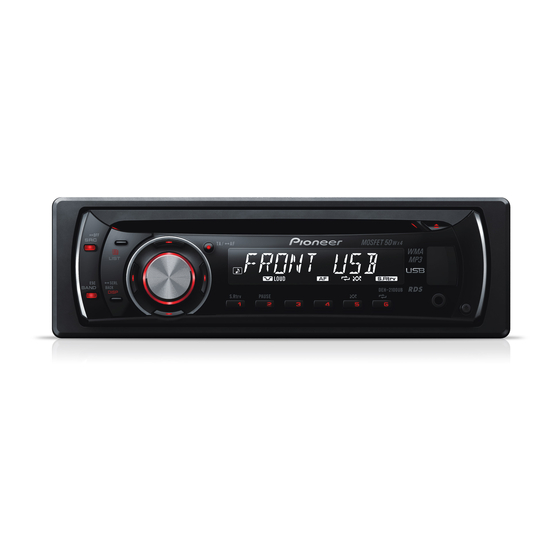
2.3 PANEL FACILITIES
Description of the unit's front panel controls, buttons, and indicators.
2.4 CONNECTION DIAGRAM
Visual representation of all external connections and their purposes.
BASIC ITEMS FOR SERVICE
3.1 CHECK POINTS AFTER SERVICING
Procedures to confirm successful repairs and product quality.
3.2 PCB LOCATIONS
Identification and location of the main Printed Circuit Boards within the unit.
3.3 JIGS LIST
List of special tools or jigs required for specific service procedures.
3.4 CLEANING
Instructions for cleaning specific parts before shipping or during maintenance.
DIAGNOSIS
5.1 OPERATIONAL FLOWCHART
Step-by-step troubleshooting guide for power-on operations.
5.2 ERROR CODE LIST
A table detailing error codes, their causes, and potential solutions.
5.3 CONNECTOR FUNCTION DESCRIPTION
Explanation of the function and pin assignment for each connector.
SERVICE MODE
6.1 DISPLAY TEST MODE
Procedure to enter and operate the display test mode for verification.
6.2 CD TEST MODE
Detailed test modes and procedures for the CD mechanism functionality.
DISASSEMBLY
Removing the Case
Steps to remove the outer casing of the unit.
Removing the CD Mechanism Module
Procedures for disassembling and removing the CD mechanism.
Removing the Tuner Amp Unit
Instructions for disassembling and removing the tuner amplifier unit.
EACH SETTING AND ADJUSTMENT
8.1 CD ADJUSTMENT
Cautions and procedures for adjusting CD mechanism settings.
8.2 CHECKING THE GRATING AFTER CHANGING THE PICKUP UNIT
Method for checking grating alignment after replacing the pickup unit.
EXPLODED VIEWS AND PARTS LIST
9.1 PACKING
Exploded view and parts list related to the product's packaging.
9.2 EXTERIOR (1)
Exploded views and parts lists for external components of the unit.
9.3 EXTERIOR (2)
Additional exploded views and parts lists for exterior components.
9.4 CD MECHANISM MODULE
Exploded view and parts list for the CD mechanism assembly.
SCHEMATIC DIAGRAM
10.1 TUNER AMP UNIT(GUIDE PAGE)
Schematic diagram for the tuner amplifier unit.
10.2 KEYBOARD UNIT
Schematic diagram for the keyboard control unit.
10.3 CD MECHANISM MODULE(GUIDE PAGE)
Schematic diagram for the CD mechanism module.
10.4 WAVEFORMS
Visual representations of key signal waveforms for diagnosis.
PCB CONNECTION DIAGRAM
11.1 TUNER AMP UNIT
Connection diagram for the tuner amplifier unit PCB.
11.2 KEYBOARD UNIT
Connection diagram for the keyboard unit PCB.
11.3 CD CORE UNIT(S10.5COMP2-USB-C3)
Connection diagram for the CD core unit PCB.
ELECTRICAL PARTS LIST
MISCELLANEOUS
List of miscellaneous electrical components and their part numbers.
RESISTORS
Comprehensive list of resistors with their circuit symbols and part numbers.
CAPACITORS
Comprehensive list of capacitors with their circuit symbols and part numbers.
Need help?
Do you have a question about the DEH-2110UB and is the answer not in the manual?
Questions and answers